


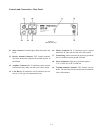
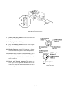
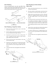

Controls and Connections - Rear Panel
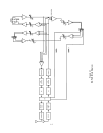
12. Relay Contacts: Normally Open. When activated it will
close.
13. Receive Antenna Connector: TNC Female connector.
The color dot near the connector must match the color of
the antenna.
14. Auxiliary Connector: RJ-12 connector used to connect
balanced auxiliary audio into and out of a base station.
15. CAN Bus: RJ-45 connectors used to connect a base sta-
tion to a CAN type of communications bus.
16. Matrix Connector: RJ-12 connector used to connect
balanced 4-W audio into and out of the base station.
17. Ground Lug: Allows customer the option to ground the
unit to a common system ground if needed.
18. Power Connector: Input power jack that requires
12 to 15 Volts AC or DC at 1000 mA.
19. Transmit Antenna Connector: TNC Female con-con-
nector. The color dot near the connector must match the
color of the antenna.
2-2
Figure 2-3
RKP-4B - Rear Panel