


CAN Bus
The CAN bus allows the connection of multiple base stations
to a Frequency Manager. The Frequency Manager then can be
used to set all the base stations to a frequency plan plus set a
variety of other options on the base station. The base stations
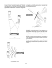
then can program frequencies of their beltpacks via an over-
the-air link. Thus a whole system can be set-up with only a
few button presses at the frequency manager. Each frequency
manager can control up to 10 base stations.
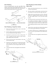
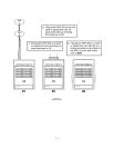
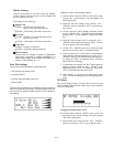
The CAN bus cable starts at the Frequency Manager and then
proceeds to the first base station. From the first base station,
the CAN bus daily chains through all the base stations, stop-
ping finally at the frequency Manager. Both base station RJ-
45 CAN bus connectors are wired in parallel so it does not
matter which jack is used for the input or output cable. See
Figure 6-4 below for a sample routing of the CAN bus cable.
NOTE: For clarity the power, interconnect, and TX/RX
cables are not shown in the figure.
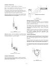
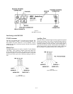
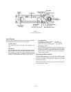
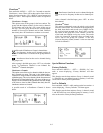
Relay
A software selectable relay closure is available at the base sta-
tion. The relay is normally open, however the base station
software options can be set so the relay closes when the belt-
pack’s relay button is pushed. The relay schematic is shown
in Figure 6-5.
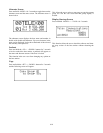
A “Phoenix” type connector (supplied) plugs into the relay
contact port on the base station. This connector provides a
screw-type closure for an easy connection to wires.
6-3
Figure 6-4
CAN Bus Cables
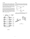
Figure 6-5
Relay Schematic
Figure 6-6
Relay Contact Jack Adapter