


Antenna Connection
The base station is supplied with two (2) antennas.
One 1/2-wave antenna for Transmit and one 1/2-wave for
Receive. The antennas have TNC male connectors.
The frequency range of the antennas should match the receiv-
er and transmitter of the base station. Match the color code on
the antenna with the color code on the base station.
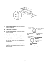
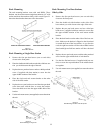
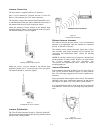
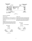
Attach the transmit 1/2-wave antenna to the antenna input
receptacle labeled “TRAN” on the right side of the rear panel.
The antenna should be vertically aligned.
Attach the receive 1/2-wave antenna to the antenna input
receptacle labeled “RCV” on the left side of the rear panel.
The antenna should be vertically aligned.
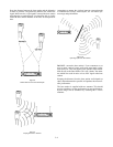
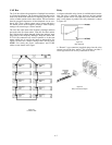
Antenna Polarization
The Telex Wireless Intercom System is “Vertically Polarized”.
This means both the transmitting and receiving antennas should
operate in the vertical position.
Distance between Antennas
The distance between the base station’s receive and transmit
antennas is not adjustable when the antennas are connected
directly on the back of the unit.
The antennas can be remoted for better signal path. A Telex
coax assembly with remote antennas may be required. See
“Accessory and Replacement Parts” section for ordering
information.
NOTE: If your base station is to be located in a shielded rack
mount enclosure or other poor RF location, you must remote
the 1/2-wave antennas with coax assemblies. See
“Accessories and Replacement Parts” section for remote
mounting hardware.
Antenna Placement
Proper antenna placement probably has the most effect on
your TELEX Wireless Intercom System’s overall perform-
ance. The following suggestions will result in optimum per-
formance.
Proper placement of the beltpack can be critical. The antennas
should be in the open. Bending the antennas up and placing
the beltpack in a pocket, etc., will reduce system distance.
It is suggested that the unit be worn on the belt or pocket with
both antenna’s vertical for best operating range and perform-
ance.
Figure 5-4
Attaching Transmit 1/2-Wave Antenna
Figure 5-5
Attaching Receive 1/2-Wave Antenna
Figure 5-6
Vertically Polarized Antennas
Figure 5-7
Proper Dressing of the Antennas
5-3