


104
MIDI Implementation
FBH
●Stop
Status
FCH
●Active Sensing
Status
FEH
* This will be transmitted constantly at intervals of approximately 250ms.
■System Exclusive Messages
* Regarding the system exclusive message refer to p. 100.
Identity reply and Data Set 1 (DT1) are the only System Exclusive messages transmitted by
HPD-15.
When an appropriate Identity Request or Data Request 1 (RQ1) message is received, the
requested internal data will be transmitted.
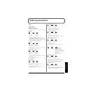
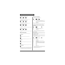
●Universal Non-realtime System Exclusive Messages
❍Identity Reply
Status Data byte Status
F0H 7EH, dev, 06H, 02H, 41H, 2EH, 01H, F7H
00H, 00H, 00H, 02H, 00H, 00H
Byte Explanation
F0H Exclusive status
7EH ID number (universal non-realtime message)
dev Device ID (dev: 00H - 1FH (1 - 32) Initial value is 10H (17))
06H 02H Identity Reply
41H ID number(Roland)
2EH 01H Device family code
00H 00H Device family number code
00H 02H 00H 00H software revision level
F7H EOX (End Of Exclusive)
* When Identity Request (p. 100) is received, Identity Reply message will be transmitted.
●Data Transmission
❍Data set 1 DT1 (12H)
Status Data byte Status
F0H 41H, dev, 00H, 2EH, 12H, aaH, bbH, F7H
ccH, ddH, eeH,... ffH, sum
Byte Explanation
F0H Exclusive status
41H ID number (Roland)
dev Device ID (dev: 00H - 1FH (1 - 32) Initial value is 10H (17))
00H 2EH Model ID (HPD-15)
12H Command ID (DT1)
aaH
Address MSB: upper byte of the starting address of the transmitted
data
bbH Address 2nd: 2nd byte of the starting address of the transmitted data
ccH Address 3rd: 3rd byte of the starting address of the transmitted data
ddH
Address LSB: lower byte of the starting address of the transmitted data
eeH Data: The actual data to be transmitted. Multiple bytes of data are
transmitted in order starting from the address.
::
ffH Data
sum Checksum
F7H EOX (End Of Exclusive)
* The amount of data that can be transmitted at once time will depend on the type of data,
and data must be requested using a specific starting address and size. Refer to the
Address and Size listed in "Parameter address map" (p. 104).
* Data larger than 128 bytes must be divided into packets of 128 bytes or less. If “Data Set
1” is transmitted successively, there must be an interval of at least 40 ms between
packets.
* Regarding the checksum please refer to p. 109.
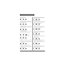
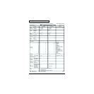
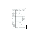
3. Parameter address map
(Model ID = 00H 2EH)
This map indicates address, size, range of data (value) and description of parameters which
can be transferred using "Data set 1 (DT1)".
All the numbers of address and size are indicated in 7-bit Hexadecimal-form. All the
numbers of data are indicated in Decimal-form.
Addresses marked at "#" cannot be used as starting addresses.
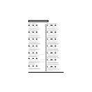
■Parameter Address Block
HPD-15 (Model ID = 00H 2EH)
+—————————————————————————————————————————————————————————————————+
|Start | |
| address | Description |
|—————————————+———————————————————————————————————————————————————|
| 00 00 00 00 | SYSTEM (Individual) 1-1|
|—————————————+———————————————————————————————————————————————————|
| 01 00 00 00 | TEMPORARY PATCH (Individual) 1-2|
|—————————————+———————————————————————————————————————————————————|
| 10 00 00 00 | SYSTEM (Bulk) 1-1|
|—————————————+———————————————————————————————————————————————————|
| 11 00 00 00 | TEMPORARY PATCH (Bulk) 1-2|
|—————————————+———————————————————————————————————————————————————|
| 12 00 00 00 | USER PATCH 01-01 (Bulk) 1-2|
| : | : |
| 12 4F 00 00 | USER PATCH 10-08 (Bulk) 1-2|
|—————————————+———————————————————————————————————————————————————|
| 20 00 00 00 | USER PATTERN (Bulk) 1-3|
+—————————————————————————————————————————————————————————————————+
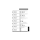
1-1 SYSTEM
+—————————————————————————————————————————————————————————————————+
|Offset | |
| address | Description |
|—————————————+———————————————————————————————————————————————————|
| 00 00 00 | UTILITY 1-1-1|
|—————————————+———————————————————————————————————————————————————|
| 01 00 00 | FOOT SW 1-1-2|
|—————————————+———————————————————————————————————————————————————|
| 02 00 00 | MIDI 1-1-3|
|—————————————+———————————————————————————————————————————————————|
| 03 00 00 | CONTROLLER 1-1-4|
|—————————————+———————————————————————————————————————————————————|
| 04 00 00 | PAD A1 1-1-5|
| : | : |
| 04 0E 00 | PAD C5 1-1-5|
|—————————————+———————————————————————————————————————————————————|
| 05 00 00 | TRIG COMMON 1-1-6-1|
|—————————————+———————————————————————————————————————————————————|
| 05 01 00 | TRIG 1 1-1-6-2|
|—————————————+———————————————————————————————————————————————————|
| 05 02 00 | TRIG 2 1-1-6-2|
|—————————————+———————————————————————————————————————————————————|
| 06 00 00 | PATCH CHAIN GROUP 1 1-1-7|
| : | : |
| 06 09 00 | PATCH CHAIN GROUP 10 1-1-7|
+—————————————————————————————————————————————————————————————————+
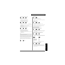
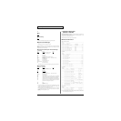
1-1-1 UTILITY
+—————————————————————————————————————————————————————————————————+
|Offset | | |
| address | Size | Description Data (Value) |
|—————————————+———————————+———————————————————————————————————————|
| 00 00 | 0000 aaaa | LCD Contrast 0 - 15 |
| | | (1 - 16) |
|—————————————+———————————+———————————————————————————————————————|
| 00 01 | 0000 aaaa | Beep Level 0 - 15 |
|—————————————+———————————+———————————————————————————————————————|
| 00 02 | 0000 000a | Dial Lock 0 - 1 |
| | | (OFF,ON) |
|—————————————+———————————+———————————————————————————————————————|
| 00 03 | 0000 000a | Power On Mode 0 - 1 |
| | | (RESET,LAST) |
|—————————————+———————————+———————————————————————————————————————|
| 00 04 | 0000 000a | Pad Chase 0 - 1 |
| | | (OFF,ON) |
|—————————————+———————————+———————————————————————————————————————|
| 00 05 | 0000 000a | Roll Sync Mode 0 - 1 |
| | | (OFF,ON) |
|—————————————+———————————+———————————————————————————————————————|
| 00 06 | 0000 00aa | Sequencer Sync Mode 0 - 2 |
| | | (Int,Ext,Remote) |
|—————————————+———————————+———————————————————————————————————————|
| 00 07 | 0000 aaaa | (Reserved) |
|—————————————+———————————+———————————————————————————————————————|
| 00 08 | 0000 000a | Pedal Select 0 - 3 |
| | | (EXP PEDAL,HI_HAT,SW +, SW -) |
|—————————————+———————————+———————————————————————————————————————|
| 00 09 | 0000 aaaa | Master Tune 0 - 509 |
|# 00 0A | 0000 bbbb | (415.3 - 466.2Hz, 0.1Hz step) |
|# 00 0B | 0000 cccc | |
|# 00 0C | 0000 dddd | |
+—————————————————————————————————————————————————————————————————+
1-1-2 FOOT SW
+—————————————————————————————————————————————————————————————————+
|Offset | | |
| address | Size | Description Data (Value) |
|—————————————+———————————+———————————————————————————————————————|
| 00 00 | 0000 aaaa | Foot Sw1 0 - 8 (*1) |
|—————————————+———————————+———————————————————————————————————————|
| 00 01 | 0000 aaaa | Foot Sw2 0 - 8 (*1) |
+—————————————————————————————————————————————————————————————————+
(*1) OFF, PATCH DOWN, PATCH UP, REV OFF/ON, M-FX OFF/ON, ROLL/HOLD,
PLAY/STOP, Mdfy SEL DN, Mdfy SEL UP