


Customizing SoundStructure Designs
5 - 11
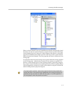
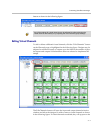
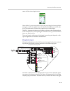
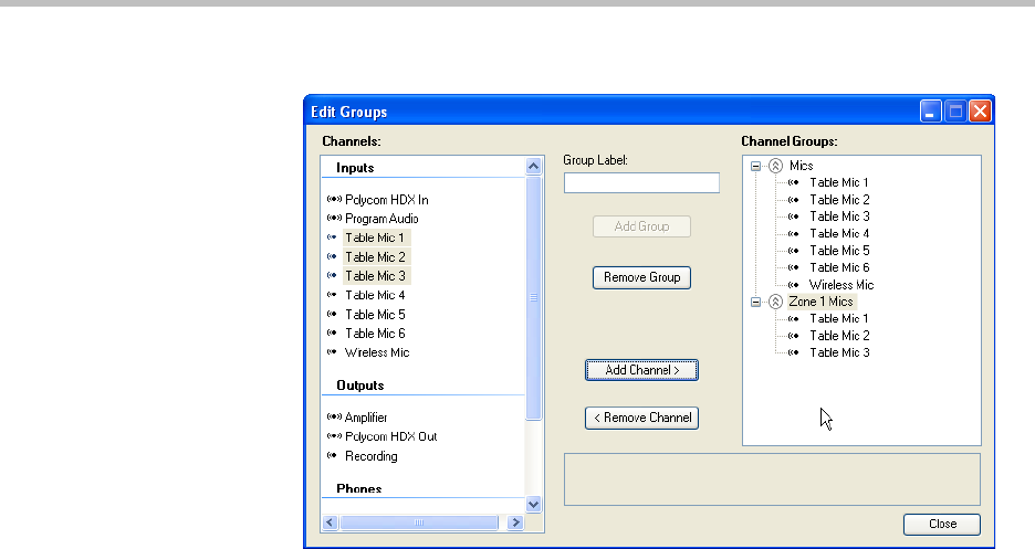
Any commands that are sent to configure the virtual channel group “Zone 1
Mics” will in turn be sent to the members of the virtual channel group. For
example if a mute command is sent to “Zone 1 Mics” then “Table Mic 1”,
“Table Mic 2”, and “Table Mic 3” will be muted and the “Zone 1 Mics” logical
group will be shown as muted.
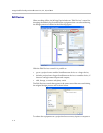
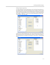
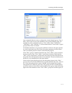
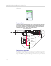
If individual members of a group have different values for the same parame-
ter, such as the mute state, the value of the group parameter will be shown
with a crosshatch pattern as shown in the following figures.
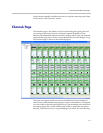
If the “Mics” group is unmuted and then the “Zone 1 Mics” group is muted,
the mute status of the “Zone 1 Mics” would show the mute status and the
“Mics” group would show a mixed mute state because some microphones in
the group were still muted but others were unmuted. The mixed mute state is
shown as a cross hatched bar in the mute button.
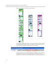
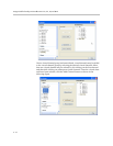
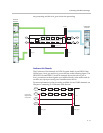
Notice in this figure that the gain for the microphone inputs in the “Mics”
group is shown as 48 with dashed lines around it indicates that some - but not
all - of the microphones have a gain of 48 dB. In this example the wireless
microphone has a different gain value. The group will show a dashed line if
not all the values are the same for the members in the group. In the following
figure the all the members of the “Zone 1 Mics” group have 48 dB of gain, so