


SoundStructure Design Concepts
3 - 19
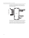
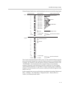
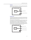
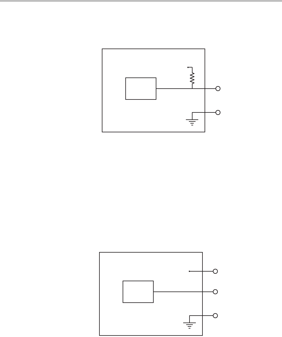
Logic Inputs
All digital logic inputs (logic inputs 1 - 22) operate as contact closures and may
either be connected to ground (closed) or not connected to ground (open). The
logic input circuitry is shown in the following figure.
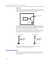
Analog Gain Input
The analog gain inputs (analog gain 1 and 2) operate by measuring an analog
voltage between the analog input pin and the ground pin. The maximum input
voltage level should not exceed +6 V. It is recommended that the +5 V supply
on Pin 1 be used as the upper voltage limit.
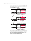
The next figure shows the analog gain input pin and the associated +5 V and
ground pins that are used with the analog gain input pin. The analog voltage
on the analog gain input pin is converted to a digital value via an 8-bit
analog-to-digital converter for use within the SoundStructure devices. The
maximum voltage value, that is, 0 dBFS on the analog gain input, is 4.096 V.
The SoundStructure API commands analog_gpio_min and analog_gpio_max
are used to map the values into a desired range of numerical values. By default
0 V is converted to 0 and 4.096 V and above is converted to 255.
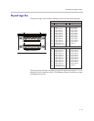
Logic
Status
SoundStructure Logic Input
Logic Input Pin
Logic Pin 25 (Ground)
3.3V
Analog
Voltage
Value
SoundStructure Logic Input
Analog Gain Input Pin
Logic Pin 25 (Ground)
Logic Pin 1 (+5V)
5V