


Connecting Over Conference Link2
6 - 13
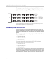
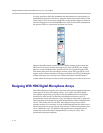
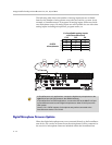
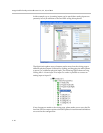
As shown in the following figure, the three microphone elements are labeled
as A, B, and C within SoundStructure Studio software environment. The
ceiling microphone arrays have an orientation dot on the band that indicates
element A. The orientation of the microphone array is only significant in stereo
or positional conferencing applications where it is important to have the
relative position of microphone elements with respect to the video
conferencing camera. See Chapter 9 for examples of stereo video conferencing
applications.
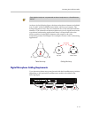
Digital Microphone Cabling Requirements
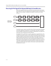
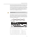
Up to four microphone arrays may be used with the SoundStructure products
depending on the particular SoundStructure model as described in the
following figure.
Each digital microphone is represented as three microphones on a SoundStructure
device.
POLYCOM
Bottom
Bottom ViewTop View
A
BC
A
BC
Orientation
Dot
C
A
B
Table Mic Array Ceiling Mic Array
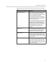
PIN 2: TXD
PIN 3: RXD
PIN 5: GROUND
PIN 7: CTS
PIN 8: RTS
LAN
C-LINK2
OBAM IR
RS-232
REMOTE CONTROL 2
IN OUT
1 2 3 4 5 6 7 8 9 10 11 12 13 14 15 16
1 2 3 4 5 6 7 8 9 10 11 12 13 14 15 16
OUTPUTS INPUTS
SoundStructure C16
TM
12V
REMOTE CONTROL 1
POLYCOM
POLYCOM
POLYCOM
POLYCOM