


Design Guide for the Polycom SoundStructure C16, C12, C8, and SR12
5 - 60
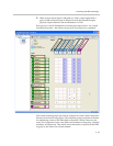
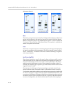
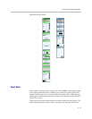
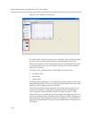
path on the SR-series), light blue indicates the sound reinforcement path,
and white indicates the ungated/recording path.
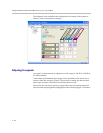
Telephony Channels
To use a telephone interface, either the SoundStructure TEL1 or TEL2 must be
included in the design and installed in the SoundStructure device.
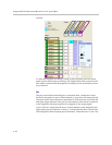
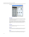
Each telephone interface that is used in the design is represented by two vir-
tual channels: one for the input telephone signal and one for the output
telephony signal. An example of these two virtual channels is shown in the fol-
lowing figure.
The signal processing paths for both the input and output channels include
equalization, dynamics processing, and audio delay. In addition, the tele-
phone input channel has noise cancellation and automatic gain control that
may be applied to the signal received from the telephone line.
The controls for both the telephone input and output channels will be
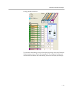
Outputs
Ungated/Recording
Conferencing
Sound Reinforcement
Ungated/Recording
Conferencing
Sound Reinforcement
Ungated/Recording
Conferencing
Sound Reinforcement
Ungated/Recording
Conferencing
Sound Reinforcement
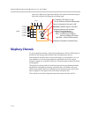
Inputs
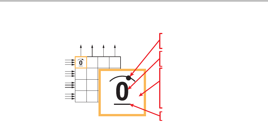
Crosspoint background indicates
version of input processing
White - Ungated/Recording
Blue - Conferencing (C-series),
Noise cancelled (SR-series)
Light Blue - Sound Reinforcement
Value of crosspoint is the gain in dB
Arc indicates L/R balance or pan
No arc indicates centered balance/pan
Underscore indicates Inverted polarity
Bold text Indicates signal is unmuted