


Design Guide for the Polycom SoundStructure C16, C12, C8, and SR12
6 - 8
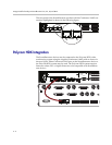
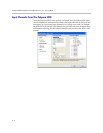
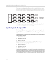
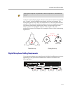
The output processing on SoundStructure that is available for these output
channels is shown in the following figure. All signals have the same process-
ing that includes dynamics, parametric equalization, fader, delay, and mute.
All the signals that are sent to the Polycom HDX system have signal level
meters that are displayed on the Channels page.
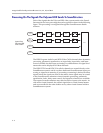
Signal Routing Inside The Polycom HDX
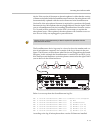
The Polycom HDX system receives the SoundStructure output signals and
internal to the HDX mixes the signals it needs to create the transmit signals to
the HDX PSTN interface and HDX Video interface. These signals are mixed as
follows:
The transmit signal to the remote video participants will be mixed within the
Polycom HDX to include:
• HDX PSTN Mix Out
• HDX Stereo Mics Out
• HDX Line Mix Out
The transmit signal to the remote telephony (PSTN) HDX participants
includes the remote video participant audio and:
• HDX PSTN Mix Out
• HDX Stereo Mics Out
• HDX Line Mix Out
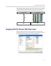
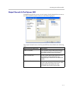
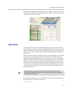
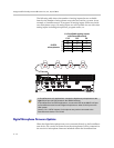
This default routing inside the Polycom HDX means that the SoundStructure
matrix does not have to add these channels to the HDX Stereo Mics Out signal.
Typically the SoundStructure matrix will look like the following figure where
the SoundStructure “Phone In” signal is routed to the “HDX PSTN Mix Out”
Matrix
HDX
Line Mix Out
Dynamics
Processing
Parametric
Equalization
Fader Delay
Mute
Dynamics
Processing
Parametric
Equalization
Fader Delay
Mute
HDX Stereo
Mics Out
Dynamics
Processing
Parametric
Equalization
Fader Delay
Mute
HDX
PSTN Mix Out
Outputs to
Polycom HDX
over CLINK2