


Connecting Over Conference Link2
6 - 23
Installation Options
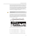
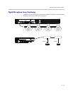
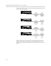
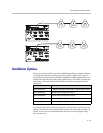
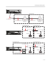
There are several installation options available depending on whether tabletop
or ceiling microphones are being used. The following figure shows typical
wiring options using the Polycom SKUs highlighted with the dashed boxes for
tabletop microphones and ceiling microphone arrays. These SKU’s include the
cables that are shown within the dashed boxes and are summarized in the
table below.
For reference, the Walta connector is the flat connector that is on the side of the
tabletop microphone arrays and the RJ45 connector is compatible with the con-
nectors on the rear of the SoundStructure device and on the digital ceiling
microphone array.
PIN 2: TXD
PIN 3: RXD
PIN 5: GROUND
PIN 7: CTS
PIN 8: RTS
LAN
C-LINK2
OBAM IR
RS-232
IN OUT
12V
PIN 2: TXD
PIN 3: RXD
PIN 5: GROUND
PIN 7: CTS
PIN 8: RTS
LAN
C-LINK2
OBAM IR
RS-232
IN OUT
12V
POLYCOM
POLYCOM POLYCOM
POLYCOM
POLYCOM POLYCOM
HDX Mic 1 HDX Mic 2 HDX Mic 3
HDX Mic 1 HDX Mic 2 HDX Mic 3
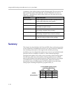
SKU Description
2215-23327-001 Tabletop microphone array with 25’ Walta to Walta cable
2215-23809-001 Black ceiling microphone array kit
2215-23809-002 White ceiling microphone array kit
2215-23810-001 Black ceiling microphone array extension kit
2215-23810-002 White ceiling microphone array extension kit