


Design Guide for the Polycom SoundStructure C16, C12, C8, and SR12
5 - 52
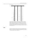
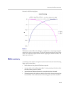
Allpass filters do not modify the gain of the signal, but change the phase. For
a second order allpass filter, the phase shift is 0 degrees at 0 Hz, 360 degrees at
high frequencies, and 180 degrees at the center frequency. The bandwidth is
defined as the bandwidth (in octaves) where the phase shift is 90 degrees and
270 degrees.
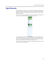
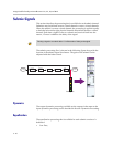
Delay
The delay processing allows the designer to add up to 1000 milliseconds of
delay on the submix signal. While the delay is set in milliseconds in the user
interface, it can be manually set through the command API in samples where
each sample represents 1/48 of a millisecond.
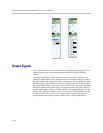
Fader
The fader control enables the user to add gain or attenuate the submix signal
from +20 dB to -100 dB with a resolution of 0.1 dB. This gain is applied in the
digital domain.
A maximum and minimum gain range can be specified for the submix faders
to limit the user gain control. The process of setting the min and max volume
controls is described in the input fader section.
The signal level meter next to the submix fader shows the signal activity after
all the submix processing has been applied. If a submix has been muted, the
signal level meter for the fader will show no signal activity.
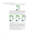
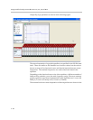
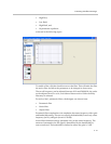
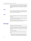
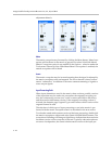
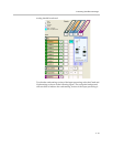
Matrix Page
The matrix page is where input virtual channels are routed to output channels
through the matrix crosspoints and crosspoint gains.
A typical matrix page is shown in the following figure with the input signals
on the left and the output signals across the top. All the unmuted crosspoints
are shown as bold and the value of each crosspoint is shown in dB. A bold 0
means that the input signal is routed to the output signal and its amplitude is
unchanged.
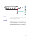
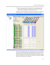
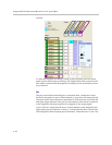
Outputs are created from inputs by summing the values in the column associ-
ated with each output signal.
Since input and output channels may be either monaural or stereo virtual
channels, there are two special cases to consider when setting crosspoint
values:
1. When a stereo input channel is mapped to a mono output channel with a
gain of 0 dB, the left and right physical channels are automatically
attenuated by 3 dB to create the mono output. The 3 dB attenuation value
is used because it is assumed the left and right signals are uncorrelated.