


Design Guide for the Polycom SoundStructure C16, C12, C8, and SR12
3 - 20
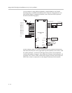
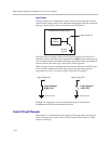
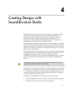
Logic Outputs
All logic outputs are configured as open-collector circuits and may be used
with external voltage sources. The maximum voltage that should be used with
the logic outputs is 60 V with a maximum current of 500 mA.
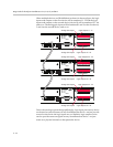
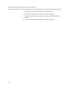
The open collector design is shown in the following figure and works as a
switch as follows: when the logic output pin is set high (on), the transistor will
turn on and the signal connected to the logic output pin will be grounded and
current will flow from the logic output pin to chassis ground.
When the logic output is set low (off), the transistor will turn off and an open
circuit will be created between the logic output and the chassis ground
preventing any flow of current as shown in the following figure.
Examples of using logic input and output pins may be found in the
SoundStructure Hardware Installation manual.
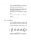
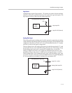
Control Virtual Channels
The concept of virtual channels also applies to the logic inputs and outputs.
The A/V designer can create control virtual channels that consist of a logic
input or output pin.
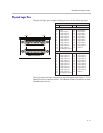
Logic
Controller
SoundStructure Logic Output
Logic Output Pin
Chassis
Ground
Logic Output
Low (Off)
Logic Output
High (On)
Chassis GroundChassis Ground
Logic Output PinLogic Output Pin