


Design Guide for the Polycom SoundStructure C16, C12, C8, and SR12
6 - 26
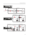
A summary of the cables is shown in the following table. The pin outs for the
RJ45 terminated cables 22457-24008-001 and 2457-24009-001 are shown in
Chapter 11 - Specifications. Both of these cables have the same pin out and
differ only in length.
Summary
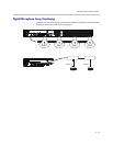
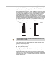
This chapter has described how the Polycom HDX video conferencing system
can be connected to SoundStructure devices over the Conference Link2 inter-
face including a description of the signals and available processing.
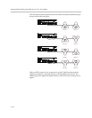
In addition, up to four digital microphone arrays may be used with the Sound-
Structure devices to simplify any audio or video conferencing design.
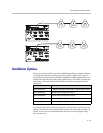
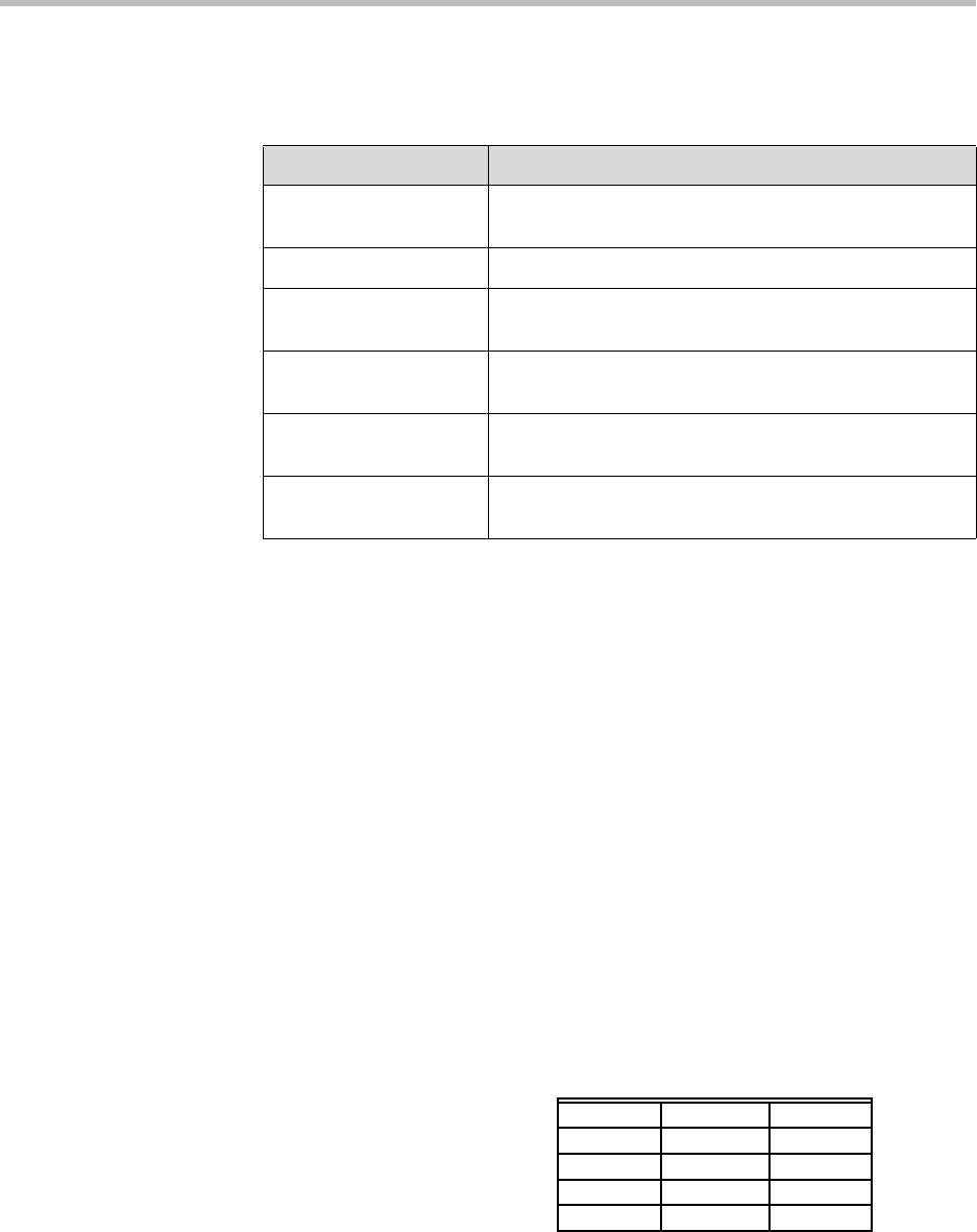
The digital microphone arrays take up the processing of three analog inputs.
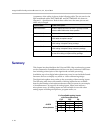
The following table shows the number of analog inputs that are available
based on the number of microphones that are used in a system. As an example,
a SoundStructure C16 supports 16 analog inputs. When used with two
microphone arrays, 10 analog inputs are still available for use with other
analog inputs including microphones, program audio, etc.
Clink2 Cable Cable Description
2457-23716-001 RJ45 to Walta connector converter. Typically included
with the HDX 9000 series video systems.
2457-23215-001 Walta to Walta cable, 15 ft length
2457-23216-001 Walta to Walta cable, 25 ft length. Included with the
HDX table microphone arrays.
2457-24008-001 RJ45 to RJ45, 50 ft length, cross-over cable. Part of the
HDX ceiling microphone array package.
2457-24009-001 RJ45 to RJ45, 25 ft length, cross-over cable. Part of the
HDX ceiling microphone array extension package.
2457-24011-001 RJ45 to RJ45, 10 ft length, straight-through cable. Part
of the HDX ceiling microphone array package.
C16 C12 C8
0
16 12 8
1
13 9 5
2
10 6 2
3
73--
4
40--
# of available analog inputs
with SoundStructure
# HDX
microphones