


12
RQT9483
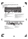
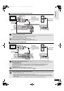
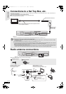
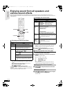
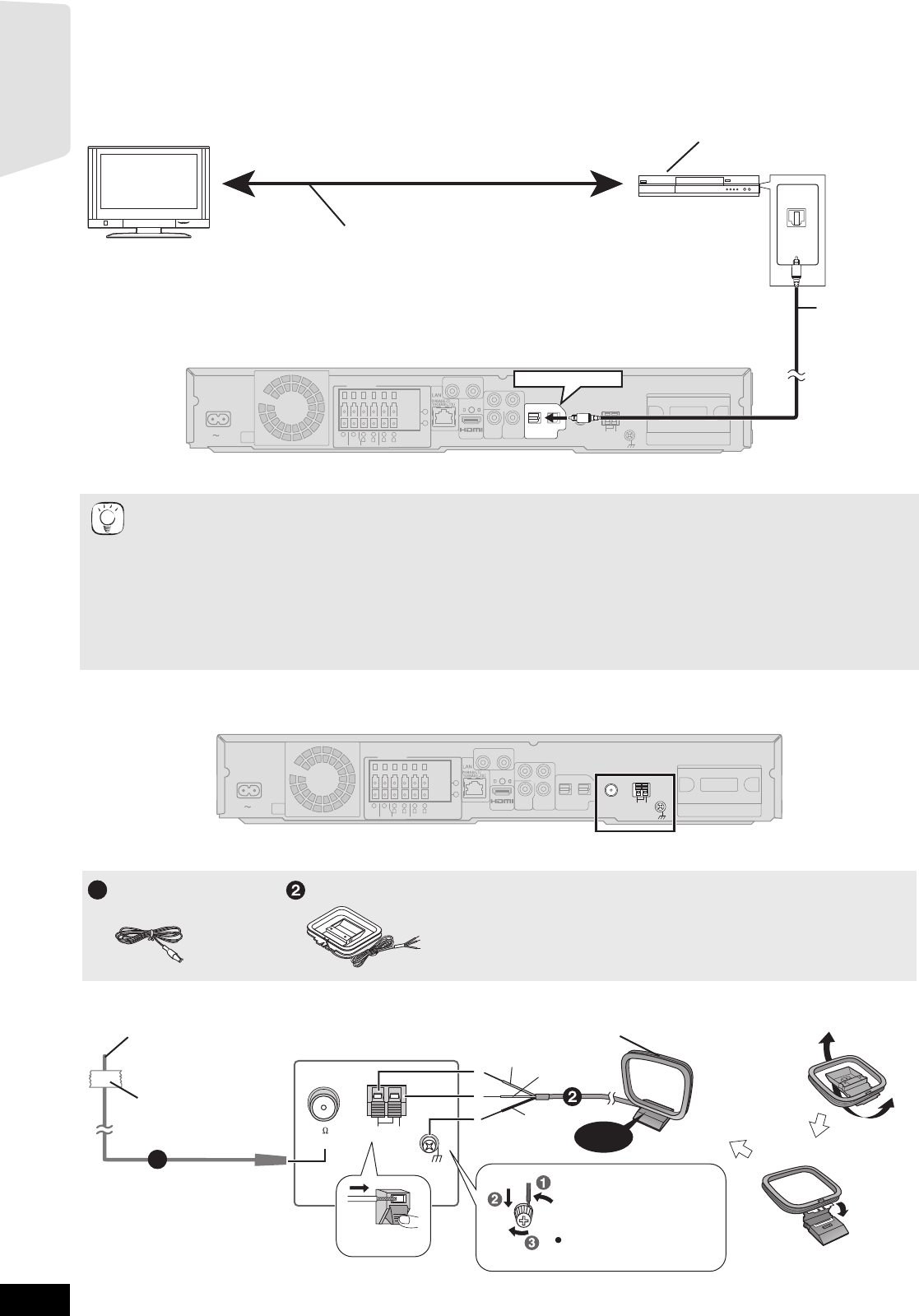
Connections to a Set Top Box, etc.
Use the following connections when you want to output the original surround audio from your Set Top Box, cable TV, VCR, DVD recorder, etc.
through this unit’s speakers.
≥Do not connect through the video cassette recorder.
Due to copy guard protection, the picture may not be displayed properly.
≥Turn off all equipment before connection.
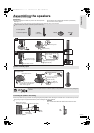
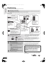
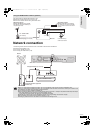
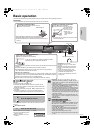
Radio antenna connections
≥Keep loose antenna cables away from other wires and cables.
≥This unit can decode the surround signal from the Set Top Box (Satellite receiver, Cable box, etc).
Press [EXT-IN] several times to select
“
D-IN 2” (DIGITAL IN 2*).
* “(CABLE/SAT)” is displayed next to DIGITAL IN 2 when set for CABLE/SAT AUDIO input. (> 29, Setting the TV audio for VIERA
Link “HDAVI Control”)
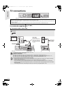
≥For connections between this unit and the TV, refer to “TV connections” (> 10, 11).
≥If you have various sound sources and this unit’s terminals are not sufficient, connect them to the available inputs on the TV and the
TV output should then be connected to the “AUX(TV)” or “OPTICAL 1(TV)” terminal of the main unit.
Refer to the operating instructions of the TV, video cassette recorder, DVD recorder or Set Top Box for settings to output its audio via
AUDIO OUT or OPTICAL OUT terminal of the TV.
–In some cases the audio signal will only be out as 2ch audio from the TV. In this case, connect the Set Top Box (Satellite receiver,
Cable box, etc.) that will be used most commonly with multi-channel audio to this unit’s “OPTICAL 2(STB)” terminal.
COMPONENT
VIDEO OUT
Y
P
R
P
B
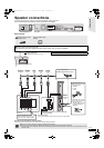
SPEAKERS
+
-
AV OUT
R
L
CENTER
3
Ω
3
Ω
FRONT
6
5
2
1
R
L
3
Ω
SURROUND
4
3
AC IN
TRANSMITTER
DIGITAL
VIDEO
OUT
OPTICAL
2(STB) 1(TV)
DIGITAL IN
L
R
AUX(TV)
ANT
EXT
LOOP
AM
GNDANTLOOP
FM ANT
75Ω
OPTICAL
OUT
OPTICAL 2(STB)
TV
Optical digital
audio cable
(not included)
STB, VCR, DVD recorder, etc.
Refer to the operating instructions of the respective devices
for the optimal connections.
Main unit
WOOFER
3
Ω
SUB-
TIPS
OPTICAL
2(STB) 1(TV)
DIGITAL IN
COMPONENT
VIDEO OUT
VIDEO
OUT
Y
P
R
PB
SPEAKERS
+
-
AV OUT
R
L
CENTER
3
Ω
3
Ω
FRONT
6
5
2
1
R
L
3
Ω
SURROUND
4
3
AC IN
TRANSMITTER
DIGITAL
L
R
AUX(TV)
WOOFER
3
Ω
SUB-
ANT
EXT
LOOP
AM
GNDANTLOOP
FM ANT
75Ω
Main unit
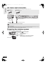
FM Indoor antenna
AM loop antenna
1
AM ANTFM ANT
EXT
LOOP
75
LOOP ANT GND
Red
White
Black
Main unit
Push!
Adhesive
tape
FM indoor antenna (included)
A
ffix this end of the antenna
where reception is best.
AM loop antenna (included)
Stand the antenna up on its base.
Place the antenna where reception is best.
Click!
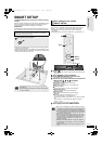
1
Use a Phillips-head
screwdriver, etc.
(not included)
Do not screw too tightly.
Getting started
SCBT207GN-RQT9483-L.book 12 ページ 2009年5月25日 月曜日 午後9時36分