


ENGLISH
22
BASIC
CONNECTIONS
BASIC OPERATION
ADVANCED
CONNECTIONS
SETUP
ADVANCED
OPERATION
TROUBLESHOOTING
OTHERS
NAMES AND
FUNCTION
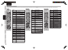
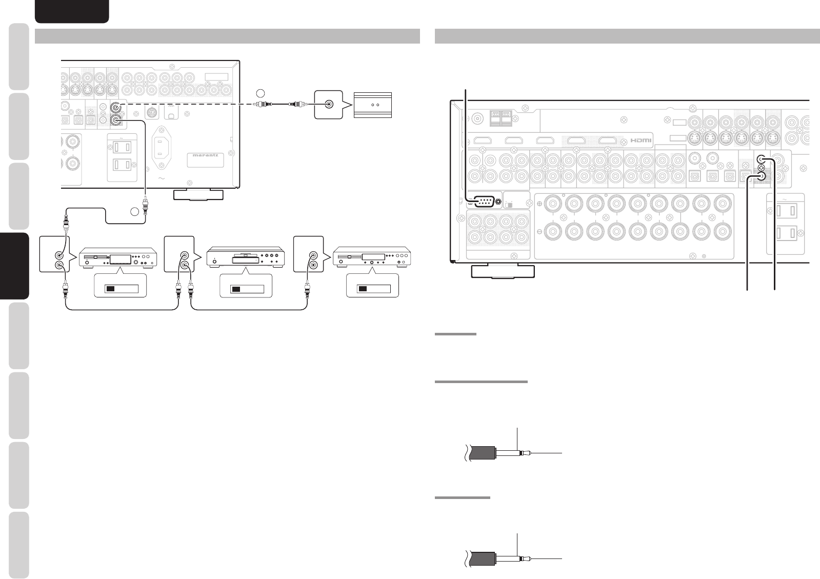
ADVANCED
CONNECTIONS
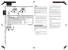
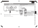
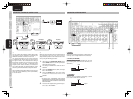
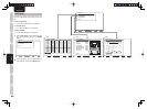
a RS-232C
Connect an external control device or other device for
servicing. (Use a straight cable for the connection.)
s DC OUT (DC TRIGGER)
External devices can be controlled from the unit
by connecting them to the DC OUT terminal (12 V
44mA max).
GND
+12V
d FLASHER IN
This unit can be controlled by connecting a control
box or other control device to this unit.
GND
Signal
R
R
R
R
L
L
L
L
R
R
L
L
L
L
R
R
AUDIO
AUDIO
INPUT
2INPUT 2
(
DVD
)
INPUT
INPUT 1
(
TV
)
MONITOR OUT
MONITOR OUT
C
C
B
B
/
/
PP
B
Y
Y
VCR OUT
VCR OUT
VCR IN
VCR IN
(
(
3
3
)
)
TV
TV
(
(
1
1
)
)
DVD
DVD
(
(
2
2
)
)
DSS
DSS
(
(
4
4
)
)
S-VIDEO
S-VIDEO
VIDEO
VIDEO
OUTPUT 2
OUTPUT 2
OUTPUT 1
OUTPUT 1
INPUT 3
INPUT 3
(
(
VCR
VCR
)
)
INPUT 2
INPUT 2
(
(
DVD
DVD
)
)
INPUT 1
INPUT 1
(
(
TV
TV
)
)
FM
FM
(
(
75
75
Ω
Ω
)
)
GND
GND
AM
AM
ANTENNA
ANTENNA
R
R
SR
SR
C
C
SW
SW
SBR
SBR
SL
SL
SBL
SBL
L
L
PRE OUT
PRE OUT
ON
ON
RS-232C
RS-232C
SPEAKER C
SPEAKER C
OFF
OFF
CENTER
CENTER
SURROUND
SURROUND
FRONT A
FRONT A
FRONT B
FRONT B
SURROUND BACK
SURROUND BACK
SPEAKER C/
SPEAKER C/
ZONE SPEAKER A
ZONE SPEAKER A
R
R
L
L
CD/CDR
CD/CDR
OUT
OUT
IN
IN
OUT
OUT
IN
IN
TAP E
TAPE
TV
TV
DSS
DSS
VCR
VCR
DVD
DVD
OUT
OUT
OUT
OUT
IN
IN
REMOTE CONT.
REMOTE CONT.
IN
IN
OUT
OUT
OUT
OUT
3
3
1
1
4
4
DIGITAL IN
DIGITAL IN
5
5
2
2
REC/ZONE B
REC/ZONE B
DIGITAL
DIGITAL
DC OUT
DC OUT
FLASHER IN
FLASHER IN
7.1CH INPUT
7.1CH INPUT
(
(
AUX 2
AUX 2
)
)
SL
SL
C
C
L
L
SBL
SBL
R
R
SR
SR
SW
SW
SBR
SBR
ZONE A
ZONE A
SPEAKER SYSTEMS
SPEAKER SYSTEMS
FRONT A OR B,CENTER, SURR,SURR BACK : 6-8 OHMS
FRONT A OR B,CENTER, SURR,SURR BACK : 6-8 OHMS
FRONT A + B : 8 OHMS
FRONT A + B : 8 OHMS
SWITCHED
SWITCHED
1.25A 150W
1.25A 150W
UNSWITCHED
UNSWITCHED
1.25A 150W
1.25A 150W
AC OUTLETS
AC OUTLETS
120V 60Hz
120V 60Hz
DC OUT
DC OUT
FLASHER IN
FLASHER IN
RS-232C
RS-232C
a
ds
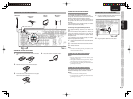
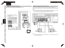
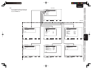
CONNECTING OTHER EQUIPMENT
L
L
OUTPUT 2
OUTPUT 2
OUTPUT 1
OUTPUT 1
INPUT 2
INPUT 2
(
(
DVD
DVD
)
)
INPUT 3
INPUT 3
(
(
VCR
VCR
)
)
INPUT 1
INPUT 1
(
(
TV
TV
)
)
COMPONENT
COMPONENT
VIDEO
VIDEO
MONITOR OUT
MONITOR OUT
C
C
R
R
/
/
P
P
R
R
C
C
B
B
/
/
P
P
B
B
Y
Y
C
C
R
R
/
/
P
P
R
R
C
C
B
B
/
/
P
P
B
B
Y
Y
C
C
R
R
/
/
P
P
R
R
C
C
B
B
/
/
P
P
B
B
Y
Y
VCR OUT
VCR OUT
VCR IN
VCR IN
(
(
3
3
)
)
VD
DVD
(
(
2
2
)
)
DSS
DSS
(
(
4
4
)
)
O
UND BACK
SURROUND BACK
E
AKER C/
SPEAKER C/
SPEAKER A
ZONE SPEAKER A
REMOTE CONT.
REMOTE CONT.
IN
IN
OUT
OUT
OUT
OUT
3
3
DIGITAL IN
DIGITAL IN
5
5
2
2
REC/ZONE B
REC/ZONE B
DIGITAL
DIGITAL
DC OUT
DC OUT
FLASHER IN
FLASHER IN
MODEL NO. SR6003
MODEL NO. SR6003
SWITCHED
SWITCHED
1.25A 150W
1.25A 150W
UNSWITCHED
UNSWITCHED
1.25A 150W
1.25A 150W
AC IN
AC IN
AC OUTLETS
AC OUTLETS
120V 60Hz
120V 60Hz
SIRIUS
SIRIUS
REMOTE CONT.
REMOTE CONT.
IN
IN
OUT
OUT
REMOTE
CONTROL
REMOTE
CONTROL
REMOTE
CONTROL
IN
OUT
IN
OUT
IN
OUT
EXTERNAL INTERNAL
EXTERNAL INTERNAL
EXTERNAL INTERNAL
1
RC OUT
2
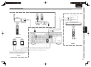
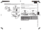
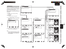
CONNECTING THE REMOTE CONTROL JACKS
DVD playerCD recorder
q
You can control other Marantz products through this
unit with the remote controller by connecting the
REMOTE CONTROL terminals on each unit.
The signal transmitted from the remote controller
is received by the remote sensor on this unit. Then
the signal is sent to the connected device through
this terminal. Therefore you need to aim the remote
control only at the unit. Also, if a Marantz power
amplifi er (some models excluded) is connected to
one of these terminals, the power amplifi er’s, power
switch is synchronized with this unit’s power switch.
Set the REMOTE CONTROL SWITCH on the back of
other units (not the SR6003) to “EXT.” (EXTERNAL)
to use this feature.
CD player
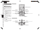
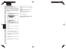
OPTION
w
Whenever external infrared sensors or similar devices
are connected to RC-5 IN of the unit, be sure to
always disable operation of the infrared sensor on the
unit by using the following procedure.
1.
Hold down the SURROUND MODE button
and the MENU button on the front panel at the
same time for fi ve seconds.
2.
The setting “IR=ENABLE” is shown on the FL
DISPLAY.
3.
Press the CURSOR buttons (1, 2) to change
this to “IR=DISABLE”.
4.
Press the ENTER button. Once this setting
is made, the infrared sensor on the unit is
disabled.
Note:
• Be sure to set to “IR=ENABLE” when external
infrared sensors or similar devices are not connected.
Otherwise, the unit will be unable to receive remote
control commands.
5.
To restore the original setting, perform steps 1
to 4 to set to “IR=ENABLE”.