


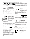
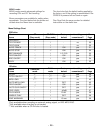
CDR
GROUND
ANALOG
IN
OUT
L
R
INPUT
SELECT
L
R
BALANCED
IN
R - TRIM - L
0
+22
0
+22
(REF=+16dBu/0dBFS)
HOT(+)
COLD(-)
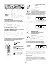
RS232C
CD
ANALOG DIG
OUT
OUT
R
L
IN
IN OUT
LOOP
OUT
DIGITAL
(SPDIF)
SERIAL NO.
THIS DEVICE COMPLIES WITH PART 15 OF THE FCC RULES.
OPERATION IS SUBJECT TO THE FOLLLOWING TWO CONDITIONS:
(1) THIS DEVICE MAY NOT CAUSE HARMFUL INTERFERENCE,
AND (2) THIS DEVICE MUST ACCEPT ANY INTERFERENCE
RECRIVED, INCLUDING INTERFERENCE THAT MAY CAUSE
UNDESIRED OPERATION.
INT.(IR)
EXT.
IN
OUT
REMOTE
(RC5)
MODEL NO. CDR510/U1B
AC120V 60HZ 0.5A
MARANTZ AMERICA INC.
1100 MAPLEWOOD DRIVE
ITASCA, IL 60143
COMPLIES WITH FDA RADIATION PERMORMANCE
STANDARDS, 21CFR SUBCHAPTER J
MANUFACTURED
WARNING: SHOCK HAZARD - DO NOT OPEN
AVIS : RISQUE DE CHOC ÉLECTRIQUIE - NE PAS OUVRIR.
MML
AC IN
RISK OF ELECTRIC SHOCK
DO NOT OPEN
MADE IN JAPAN
U
L
C
US LISTED
AUDIO SYSTEM
69FM
CAUTION
FACTORY CODE
NO 4300
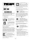
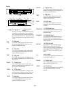
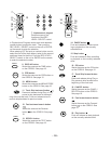
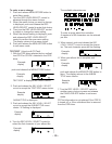
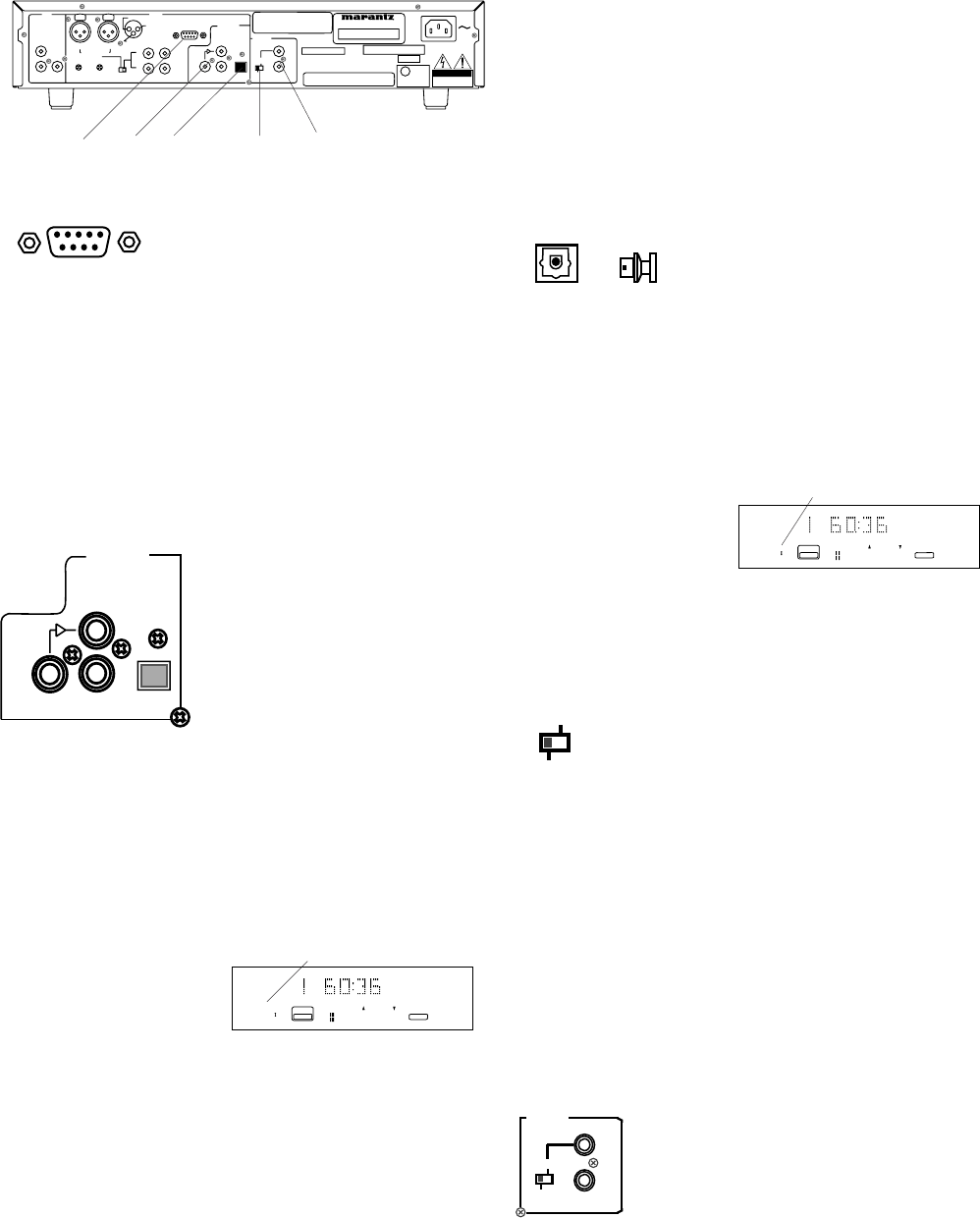
7. RS-232C connector
Using serial communication, a
host device can control the
CDR510.
7 8 9 10 11
- 24 -
RS232C
• The RS-232C host can control functions of
the CDR510 externally.
• The CDR510 automatically transmits status
data when status is changed.
• The CDR510 will respond to a status request
by transmitting the associated status data.
See RS-232C control for details.
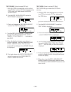
IN
IN OUT
LOOP
OUT
DIGITAL
(SPDIF)
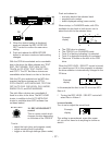
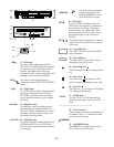
8. DIGITAL IN & OUT
connectors (SPDIF)
Digital audio cable with
RCA jacks can be used
for input and output.
Optical cable can be
used for input.
DIGITAL IN jack (RCA)
Connect a digital audio cable with RCA jacks
from an external device providing SPDIF digital
output. To record from this input DIGITAL must be
selected by pressing and releasing the INPUT
button on the front of the CDR510 so DIGI is
displayed.
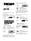
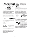
Example
display
DIGI
1
CD - R
L
R
TOTAL
CD
CHANGER
OPT
To avoid interference and noise, do not use the
DIGITAL IN (RCA) jack and the DIGITAL IN
(optical) connector at the same time.
DIGITAL LOOP OUT jack (RCA)
Connect a digital audio cable with RCA jacks to
an external device accepting a SPDIF digital
input. This connection will pass an input digital
signal as long as the CDR510 is powered on,
even if the CDR510 is not recording or in play-
back.
DIGITAL OUT jack (RCA)
Connect a digital audio cable with RCA jacks to an
external device accepting a SPDIF digital input.
This connection will pass a digital signal when the
CDR510 is recording, when the CDR drive is in
playback, and in CHANGER mode when the CD
drive is in playback.
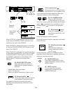
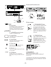
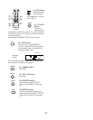
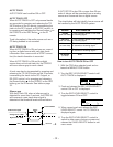
9. DIGITAL IN connector
(optical)
Remove the dust cover and
plug a digital optical cable in
here.
IN
To record from this input OPTICAL must be
selected by pressing and releasing the INPUT
button on the front of the CDR510 so OPTI is
displayed.
Example
display
OPTI
1
CD - R
L
R
TOTAL
CD
CHANGER
OPT
To avoid interference and noise, do not use the
DIGITAL IN (RCA) jack and the DIGITAL IN
(optical) connector at the same time.
IN
OUT
REMOTE
(RC5)
INT.(IR)
EXT.
INT.(IR)
EXT.
10. EXT / INT (IR) switch
Switch to select between the INT
(IR), internal infrared, remote
control, left switch position, and the EXT, external
(RC5) remote control, right switch position.
IR Remote control model RC2100 DR is sup-
plied.
Note:
When the RC-5 is not used, leave the switch in
the INT (IR) position. If desirable, for example in
a professional studio, to disable the IR receiver,
leave the switch in the EXT position.
11. REMOTE (RC5) IN / OUT
jacks (RCA)
Use the supplied cable to connect
the IN jack to a remote control
generator.