


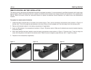

Basic Operation
JBL
2-8
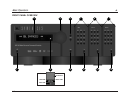
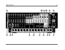
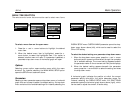
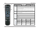
Rear Panel Overview (continued from page 2-7)
10.Main Zone Video Output Connectors
Provide video output in the Main Zone. Two composite video
connectors, two S-video connectors, and one component
video connector (BNC) are available. The composite and
S-video connectors labeled 1 (OSD) incorporate the on-screen
display.
Note:
• Composite video output connectors are available
when a composite or S-video source is present.
• S-video output connectors are available when an
S-video source is present.
• Component video output connectors are available
when a component video source is present.
11.Record Zone Video Output Connectors
Provide video output in the Record Zone. Two composite video
connectors and two S-video connectors are available.
Alternatively, these connectors can be used to connect a video
recording device.
12.RS-232 Connectors
Provide serial control. The RS-232 connector labeled 1 is
provided to perform flash memory software upgrades and
configuration downloads. The RS-232 connector labeled 2 is
provided to support future expansion.
13.Trigger Output Connectors
Provide 12V DC output to control connected components.
Three trigger output connectors are available on a removable
terminal block. The connector labeled PWR – the power trigger
output connector – is not configurable. It is activated when the
SDP-40 is activated, and deactivated when the SDP-40 is
deactivated. The trigger output connectors labeled 1 and 2 can
be configured for remote or program operation.
14.IR IN Connector
Accepts input of IR signals from infrared distribution equipment.
One 3.5mm jack that accepts a stereo plug (Tip/Ring connection)
or mono plug (Tip/Sleeve connection) is available.
15.Microphone Input Connectors
Provided for future expansion. Four 3.5mm T/R/S or balanced
inputs are available.
16.Removable Access Panel
Accommodates connectors for emerging technologies.