


Basic Operation
SDP-40
2-5
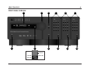
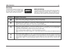
8. Main Zone Off Button
Deactivates the Main Zone.
9. Zone 2 Input Selection Buttons
Selects the input in Zone 2. When an input is selected, an
amber LED lights on the corresponding input selection button.
When Zone 2 is deactivated, pressing a Zone 2 input selection
button activates Zone 2 and selects the corresponding input.
The Main and Record Zones remain deactivated until a Main or
Record Zone input is selected.
10.Zone 2 Off Button
Deactivates Zone 2.
11.Record Zone Input Selection Buttons
Selects the input in the Record Zone. When an input is selected,
a red LED lights on the corresponding input selection button.
When the Record Zone is deactivated, pressing a Record Zone
input selection button activates the Record Zone and selects
the corresponding input. The Main Zone and Zone 2 remain
deactivated until a Main Zone or Zone 2 input is selected.
12.Record Zone Off Button
Deactivates the Record Zone.
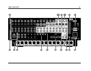
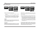
REAR PANEL OVERVIEW
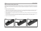
1. Power Switch
Connects power to the AC input connector and disconnects
power from the AC input connector. The c represents the "off"
position and the|represents the "on" position. When the
SDP-40 is powered on, the standby button can be used to
activate and deactivate standby mode. When the SDP-40 is
powered off, standby mode is not available.
2. AC Input Connector
Provides power to the SDP-40 through the supplied power
cord (3 wire, 10 amp, IEC 320).
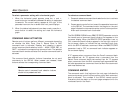
3. Digital Audio Input Connectors (S/PDIF & AES/EBU)
Provide digital audio input in all zones. Six S/PDIF coaxial,
six S/PDIF optical (Toslink), and one AES/EBU (XLR) input
connectors are available. These connectors are compatible with
PCM (44.1, 48, 88.2, and 96kHz), Dolby Digital, and dts(-ES)
sources. These connectors are not compatible with MPEG or
MP3 sources.
4. Analog Audio Input Connectors
Provide analog audio input in all zones. Eight stereo analog
audio input connectors labeled 1 to 8 are available. The
connectors labeled 6, 7, and 8 can be configured as a 5.1-
channel connector.
When a 5.1-channel analog audio source is present in the Main
Zone, input signals are sent to the Main Zone audio output
connectors as indicated in the table on page 2-7.