


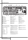
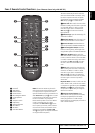
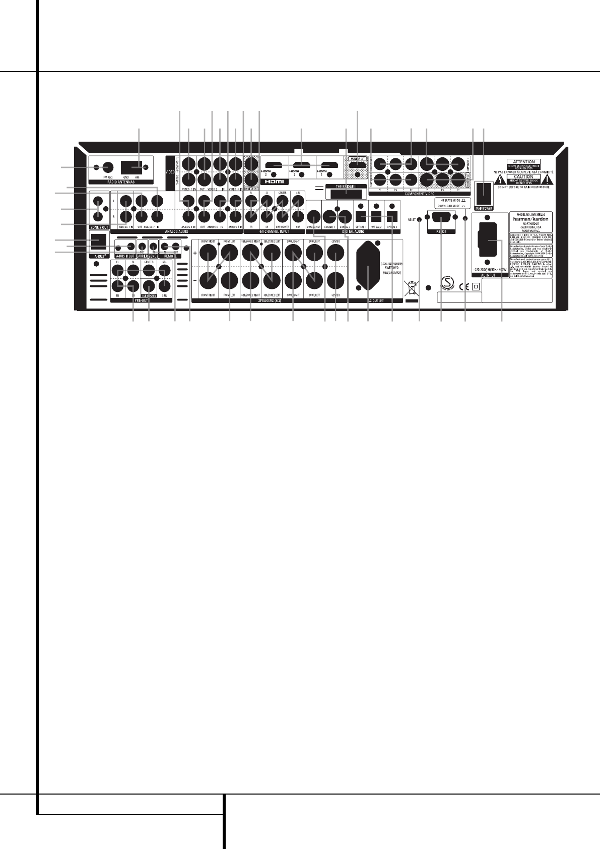
Rear Panel Connections
0
Z
Q
P
7
T
S
Y
5
B
9
a
8
X
L
J
eK
g
I
W
4VU
DO F
A
E
N
G
R
C
HM
1
2
3
b
6
c
f
d
0
1
2
3
4
5
6
7
8
9
A
B
C
D
E
F
G
H
I
J
K
L
M
N
O
P
Q
R
S
T
U
V
W
X
Y
Z
a
b
c
d
e
f
g
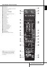
AM Antenna
FM Antenna
Analog 2 Audio IN
Analog 2 Audio OUT
Subwoofer Output
Analog 5 Audio IN
Analog 1 Audio IN
Analog 4 Audio OUT
Bridge II Connector
(Stereo Jack IN AVR 255)
8-Channel Direct Inputs
Digital Audio Outputs
Video Monitor Outputs
Reset Button
Front Speaker Outputs
Center Speaker Outputs
Surround Speaker Outputs
Switched ACAccessory Outlet
RS-232 Serial Port
AC Power Cord
Video 2 ComponentVideo Inputs
Component Video Outputs
Video 1 ComponentVideo Inputs
Download Mode Button
Coaxial Digital Inputs
Surround Back/Multiroom Speaker Outputs
Video 2Video Outputs
Video 1Video Inputs
Optical Digital Inputs
Analog 4 Audio IN
Video 2Video Inputs
Remote IR Output and Input
Zone 2 IN
Preamp Outputs
HDMI Output
Video 3Video Inputs
Analog Audio 3 IN
HDMI Inputs
Zone 2 OUT (AVR 355 only)
A-BUS Connector (AVR 355 only)
Remote IR Carrier Out (AVR 355 only)
Video 3 ComponentVideo Inputs
(AVR 355 only)
A-BUS IR Out (AVR 355 only)
Main Power Switch
NOTE: To assist in making the correct connec-
tions for multichannel input/output and speaker
connections, all connection jacks and terminals
have been color coded in conformance with the
latest CEA standards as follows:
Front Left: White
Front Right: Red
Center: Green
Surround Left: Blue
Surround Right: Gray
Surround Back Left: Brown
Surround Back Right: Tan
Subwoofer (LFE): Purple
Digital Audio: Orange
Composite Video: Yellow
Component Video “Y”: Green
Component Video “Pr”: Red
Component Video “Pb”: Blue
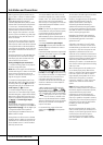
0
AMAntenna:Connect theAM loop antenna
supplied with the receiver tothese terminals.If an
externalAMantennais used,make connections to
the AM and GND terminals in accordance with
the instructions supplied with the antenna.
1
FMAntenna: Connect the supplied indoor or
an optional external FM antenna to thisterminal.
2
Analog 2 IN: Connect these jacks to the
PLAY/OUT audio jacks on any audio or video
source.
3
Analog 2 OUT: Connect these jacks to the
REC/IN audio jacks on any audio or video source.
4
Subwoofer Output: Connect this jack to
the line-level input of a powered subwoofer. If an
external subwoofer amplifier is used,connect this
jack to the subwoofer amplifier input.
5
Analog 5 IN: Connect these jacks to the
PLAY/OUT audio jacks on any audio or video
source.
6
Analog 1 IN: Connect these jacks to the
PLAY/OUT audio jacks on any audio or video
source.
7
Analog 4 OUT: Connect these jacks to the
REC/IN audio jacks on any audio or video source.
8 REAR PANEL CONNECTIONS