


LBI-39101 BOARD SET-UP
6
PERSONAL COMPUTERS
In most cases, the Personal Computer (PC) used with
the C3 Maestro console is delivered with its hard disk drive
formatted and MS-DOS
®
operating system software
installed on the hard disk drive. In addition, all C3 Maestro
application software is also installed on the drive.
Hardware
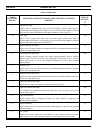
Table 1 lists the PCs approved for use with a
C3 Maestro console system equipped with an Enhanced
Audio Enclosure. Use of an unapproved computer will void
the console system's warranty and support services.
Subsequent to the printing of this manual, additional PCs not
listed in the table may be approved.
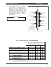
Table 1
−−
Approved Personal Computers
MANUFACTURER MODEL NO. OR TYPE
Hewlett-Packard
Vectra VE Series 2 5/75
(Pentium/75 MHz)
Hewlett-Packard
Vectra VE 5/75
(Pentium/75 MHz)
Hewlett-Packard Vectra VL2 (486/66 MHz)
Hewlett-Packard Vectra 25N (486/25 MHz)
Hewlett-Packard 486SX/25 (486SX/25 MHz)
Operating System Software
The PC will have MS-DOS version 6.x installed on its
hard drive. Earlier versions of MS-DOS are not approved
for use with the C3 Maestro console system equipped with
an Enhanced Audio Enclosure.
Unless otherwise noted, all procedures in this
manual should be performed in the order presented.
BOARD SET-UP
ENHANCED AUDIO ENCLOSURE
Normally, the Enhanced Audio Enclosure is configured
at the factory for a standard C3 Maestro dispatch console
system installation. This configuration includes setting a
single 4-position DIP switch and programming all digital
pots for nominal audio input and output levels. The DIP
switch and digital pots within the Enhanced Audio
Enclosure are located on the Audio System Board.
In most cases, changes to the factory DIP switch
and digital pot settings ARE
NOT
REQUIRED.
The following information lists the normal
factory settings and the optional settings which
are available. Digital pot setting changes must
be accomplished
after
most of the installation
procedures presented later in this manual are
complete and the console has been powered-up.
However, for completeness of this section, a
setting procedure is included on page 7.
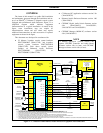
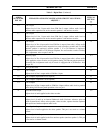
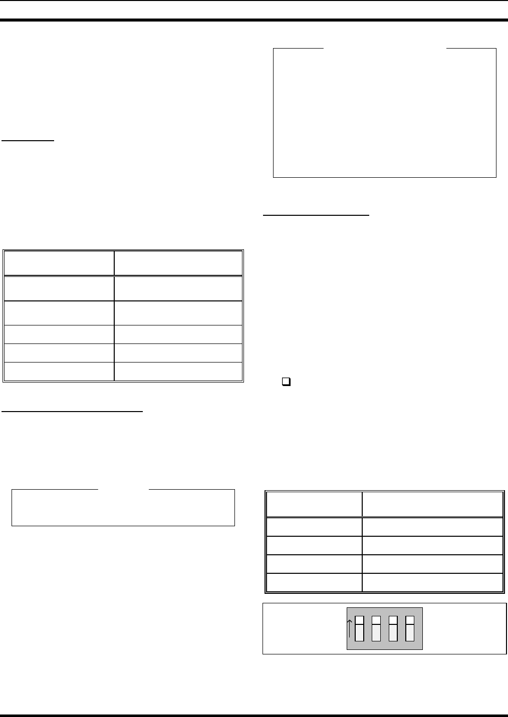
Audio System Board
Mic Audio ALC Enable/Disable DIP Switch (S1)
DIP switch S1 on the Audio System Board is used to
independently enable or disable each microphone's
automatic level control (ALC) circuit. The switch has four
(4) positions, one for each mic that may be connected to the
Enhanced Audio Enclosure.
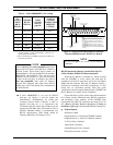
An Audio System Board ships from the factory with all
mic audio ALC circuits enabled. As shown in Figure 2, this
is accomplished by setting all four S1 switch positions to
"ON" or "CLOSED". Table 2 lists each switch position and
its corresponding microphone.
Normally, mic audio ALC should not be disabled.
However, if required, disable a mic's ALC by
setting the corresponding DIP switch position to
"OFF" or "OPEN". See LBI-39100 for Enhanced
Audio Enclosure disassembly and Audio System
Board access instructions.
Table 2
−−
Audio System Board Mic Audio ALC
Enable/Disable DIP Switch S1
S1 POSITION MICROPHONE
1 Operator Headset
2 Desk
3 Boom/Gooseneck
4 Supervisor Headset
Figure 2
−−
Audio System Board DIP Switch S1
Factory Setting (ALC Enabled On All Mics)
ON
12 3
4
NOTE
IMPORTANT NOTE