


LBI-39101 BOARD SET-UP
10
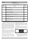
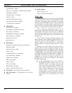
Table 3 – Digital Pots
AUDIO
SYSTEM BD.
POT NO.
ENHANCED AUDIO ENCLOSURE AUDIO CIRCUIT LOCATED IN /
ADJUSTS *
TYPICAL
SETTING
**
23 Unselect Speaker 2 Output
Adjusts level of audio applied to the second unselect speaker (unselect speaker 2). This
pot is not used as a volume control.
128
24 Unselect Speaker 3 Output
Adjusts level of audio applied to the third unselect speaker (unselect speaker 3). This
pot is not used as a volume control.
128
22 Unselect/Telephone Recorder Output
Adjusts level of audio applied to the unselect recorder. This audio may be from an
unselect source or from the Call Director's telephone line.
175
2 Call Director Output
Adjusts level of audio to Call Director's telephone line (from radio). Also see pot 18.
130
25 Supervisor Headset Earphone Output
Adjusts level of audio applied to the supervisor headset earphones. This pot is not used
as a volume control.
20
26 Operator Headset Earphone Output
Adjusts level of audio applied to the operator headset earphones. This pot is not used as
a volume control.
20
* See Audio System Board maintenance manual for specific test points and additional alignment information.
**Numbers represent typical digital pot settings only. Factory settings are subject to change without notice as circuit improvements
occur. DO NOT ADJUST any digital pot from factory setting unless a full understanding of the consequences is known.
Specifically, with the volume control fully
counterclockwise and a nomimal audio level of 436
millivolts rms at a frequency of 1kHz from the Enhanced
Audio Enclosure, the audio output level from the speaker
will not drop below approximately 0.38 milliwatts or 55
millivolts rms across the 8-ohm speaker. This wattage figure
assumes SW1 position 2 is also "OFF" or "OPEN",
selecting the 2-watt maximum volume level. With SW1
position 2 selecting 5-watts, the minimum volume level is
approximately 1.25 milliwatts or 100 millivolts across the 8-
ohm speaker.
When SW1 position 1 is "ON" or "CLOSED", the
minimum volume level feature is disabled and audio from
the speaker may be completely turned off by rotating the
volume control fully counterclockwise. This setting should
be used with caution since calls, especially calls on unselect
audio channels, are more likely to be missed.
Maximum Volume Level DIP Switch (SW1 Position 2)
SW1 position 2 allows setting of the speaker's
maximum volume level to either 2 or 5 watts of output
power. Normally, the factory setting is 2 watts. This level is
recommended, as it should be adequate in nearly all dispatch
environments. The 2-watt setting is selected by setting the
switch "OPEN" or "OFF". When the switch is "CLOSED"
or "ON", the maximum output power is increased to
approximately 5 watts.
Both wattage figures assume the volume control on the
Speaker Assembly's front panel is set at maximum (fully
clockwise) and a nominal audio signal input level of 436
millivolts rms at a frequency of 1 kHz is applied to the
Speaker Assembly.
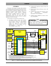
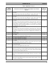
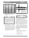
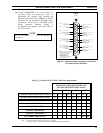
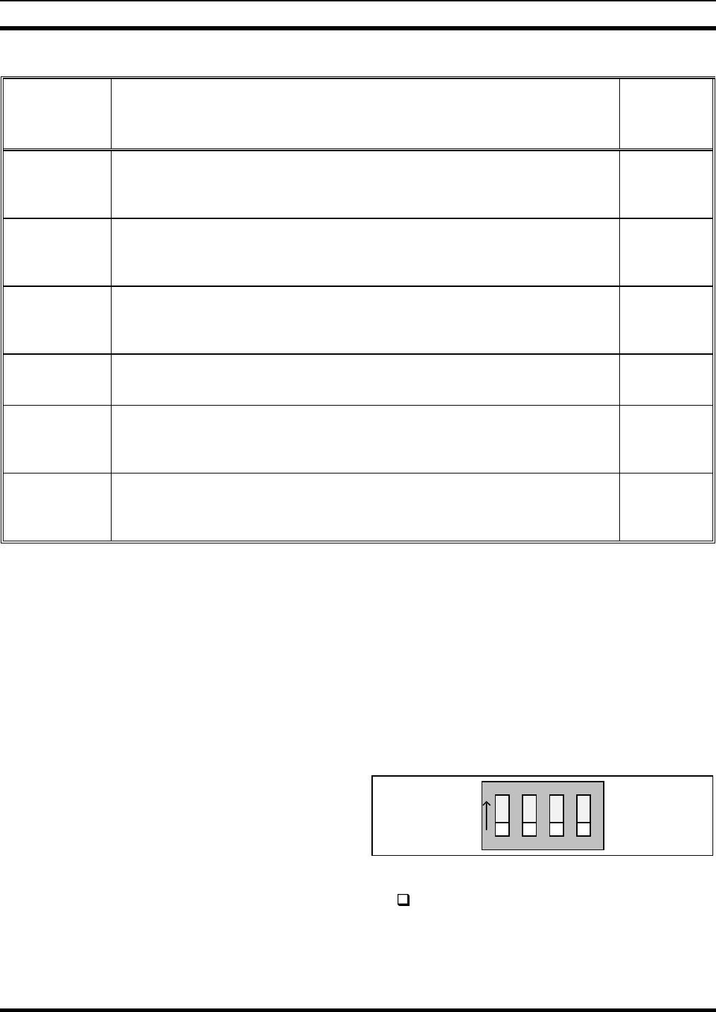
ON
12 3
4
Figure 3 −− Speaker Amp Board SW1 Factory Setting
At this time, configure SW1 as required. If the
Speaker Assembly is a desktop (with case) style,
disassemble it by removing the four (4) screws
from the back of the case and then separate the
case's front and rear sections.
(Continued)