


LBI-39101 ENHANCED AUDIO ENCLOSURE CONNECTOR PIN-OUTS
30
•
defining the event for input or output operation
(event type)
•
defining the event’s CEC/IMC Controller Board
utilized (device type and device assignment
number) and the I/O bit number used on this
Controller Board
•
including or not including each console in the
event’s “console mask”
•
defining the event’s active state as either high or
low
•
for an input event, defining a text message which is
sent to the console(s) when the event is triggered
(when it transitions to the active state)
•
for an output event, defining if it will operate with
momentary or toggle action, and defining which
console keystroke or other trigger signal controls
the event
Refer to the appropriate manual listed in Table 11
and/or the CEC/IMC Manager’s on-line help for
configuration details. Also see LBI-38938.
If a C3 Maestro console is granted monitoring/control
capability of auxiliary I/O events via “console mask”
definitions, it can monitor input event transitions and it can
control output event transitions. For auxiliary input events,
text messages display in the bottom left corner of the
console’s display. Auxiliary output events are controlled via
<Alt><F1> thru <Alt><F8> keystrokes from the console’s
dispatch keyboard.
SOFTWARE INSTALLATION AND
UPGRADES
As previously stated, all C3 Maestro application
software is installed on the PC's hard disk drive at the
factory. Refer to publication SRN-1000-xx which is
included with a software upgrade package if a re-installation
or an upgrade is necessary.
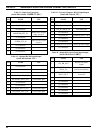
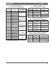
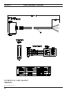
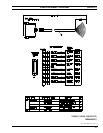
ENHANCED AUDIO ENCLOSURE
CONNECTOR PIN-OUTS
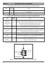
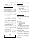
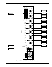
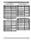
Tables 12 thru 28 that follow list the pin-outs of the
connectors on the Enhanced Audio Enclosure's rear panel.
"
NAME
" designations in the tables correspond to the
labeling used on the I/O Backplane Board schematic
diagram. Figure 11 shows the rear panel and serves as a
guide to the desired table(s).
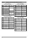
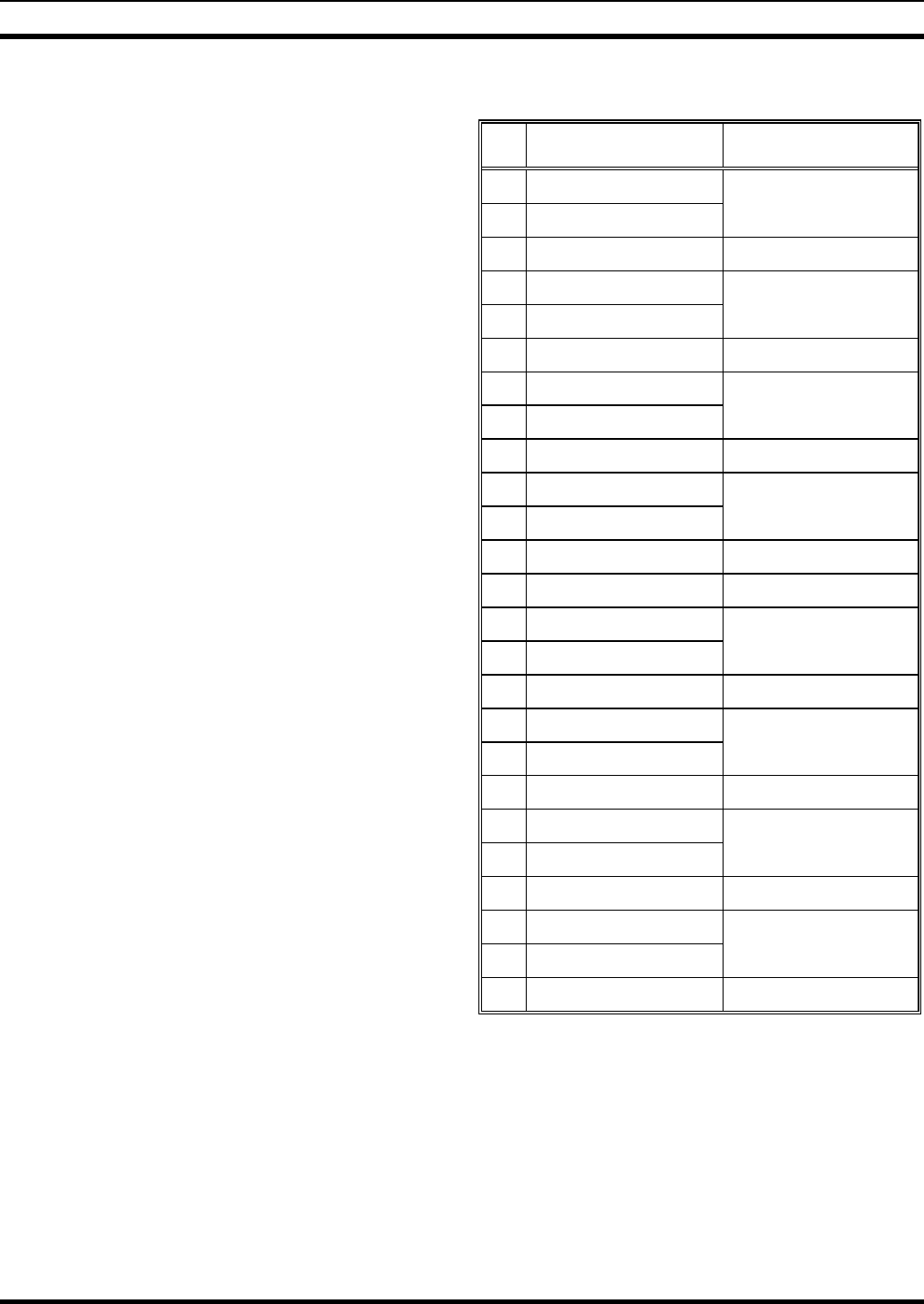
Table 12 – CEC/IMC Audio Lines
(female DB-25 labeled "
LINES 1-4
")
PIN NAME USE *
1 LINE_1_IN+
Line 1
2 LINE_1_IN-
balanced input
3 no connection
4 LINE_2_IN+
Line 2
5 LINE_2_IN-
balanced input
6 no connection
7 LINE_3_IN+
Line 3
8 LINE_3_IN-
balanced input
9 no connection
10 LINE_4_IN+
Line 4
11 LINE_4_IN-
balanced input
12 no connection
13 no connection
14 LINE_1_OUT+
Line 1
15 LINE_1_OUT-
balanced output
16 no connection
17 LINE_2_OUT+
Line 2
18 LINE_2_OUT-
balanced output
19 no connection
20 LINE_3_OUT+
Line 3
21 LINE_3_OUT-
balanced output
22 no connection
23 LINE_4_OUT+
Line 4
24 LINE_4_OUT-
balanced output
25 no connection
* With respect to the Enhanced Audio Enclosure. For
example, pins 1 and 2 are Enhanced Audio Enclosure line
inputs; audio signals on these inputs originate from the
CEC's/IMC's CIM line outputs. Also see Figure 5.