


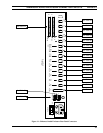

LBI-39101 ENHANCED AUDIO ENCLOSURE CONNECTOR PIN-OUTS
34
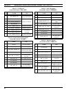
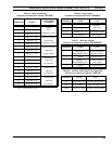
Table 21 – Supervisor Footswitch
(female DB-9 labeled "SUPER FT. SW.")
PIN NAME USE
1 no connection
2 PS_GND_IN ground for pins 4 & 6
3 no connection
4 MONITOR_PTT_IN
monitor PTT (enable)
input; see pin 2
5 no connection
6 SUPER_PTT_IN
Supervisor PTT input;
see pin 2
7 no connection
8 no connection
9 no connection
Table 22 – Optional RS-422 Input/Output
(female DB-9 labeled "I/O")
PIN NAME USE
1 no connection
2 no connection
3 no connection
4 TX_RS485_DATA_OUT+ ½ serial data output
5 RX_RS485_DATA_IN+ ½ serial data input
6 no connection
7 no connection
8 TX_RS485_DATA_OUT- ½ serial data output
9 RX_RS485_DATA_IN- ½ serial data input
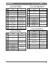
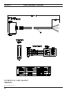
Table 23 – Personal Computer RS-232 Input/Output
(female DB-9 labeled "PC")
PIN NAME USE
1 no connection
2 TX_PC_DATA_OUT serial data output
3 RX_PC_DATA_IN serial data input
4 no connection
5 PS_GND_IN ground for pins 2, 3 & 8
6 no connection
7 no connection
8 POWER_STATUS_OUT power-up status output
9 no connection
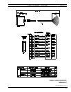
Table 24 – Dispatch Keyboard Serial Input/Output
(female DB-9 labeled "KBD")
PIN NAME USE
1 +5V_KB_OUT
keyboard dc power
output
2
RX_KEYBOARD_
DATA_IN
serial data input
(data from keyboard)
3
TX_KEYBOARD_
DATA_OUT
serial data output
(not used)
4 PS_GND_IN ground for pins 1, 2 & 3
5 no connection
6 no connection
7 no connection
8 no connection
9 no connection
* See Table 9 for wire color coding.