


LBI-39101 INTERCONNECTING THE EQUIPMENT
12
Switch Customer-Specific System Documentation
maintenance manual, LBI-38939 for sample print-outs and
complete print-out explanations.
Control Data Link
Overview
Either an RS-422 (four-wire) or an RS-232 (three-wire)
full-duplex serial control data link may be employed
between the console and the CIM within the CEC/IMC.
Since RS-422 interfacing is superior to RS-232, PCs used
within the C3 Maestro console application normally ship
from the factory with an RS-422 serial port provided for this
purpose. RS-232 has poorer noise performance than RS-422
and therefore, it should never be used for cable runs more
than 50 feet (15.2 meters) in length. RS-422 connections
may be up to 4000 feet (1219 meters) in length.
If required for a remote console installation, full-duplex
4-wire data modems can be used between the C3 Maestro
and the CEC/IMC. Typically, the PC-to-modem and
modem-to-CEC/IMC interconnections must be made via
RS-232 interconnections since many data modems do not
provide RS-422 hook-ups. These RS-232 interconnections
should also not exceed 50 feet. See the following
subsections for additional remote console wiring and modem
configuration details.
At the C3 Maestro, RS-422/RS-232 serial control data
connections terminate at the PC's serial COM port.
Normally, COM1 is utilized for CEC/IMC interfacing. This
serial port is normally provided by a plug-in RS-422 board
inside the PC as described in the following section.
RS-422 Interfacing (Co-Located Hook-Ups)
In most cases, the PC used in the C3 Maestro console
system is not equipped with a main ("mother") board
RS-422 capable serial COM port. Therefore, a plug-in
RS-422 capable interface board is installed in one of the
PC's internal expansion slots and utilized for CEC/IMC
interfacing. If the plug-in RS-422 board's serial port is
configured as COM1 (normal factory configuration), the
PC's main board COM1 port is disabled to prevent conflicts.
Likewise, if the plug-in RS-422 board's serial port is
configured as COM2, the PC's main board COM2 port is
disabled. Depending upon the type of PC used, disabling of
the main board's COM port is done via either a DIP switch,
jumper, or a BIOS set-up program. For COM port
enable/disable configuration details, refer to the section
entitled "
SOFTWARE INSTALLATION AND SET-UP
PROCEDURE
", subsection "
PC CMOS SET-UP
PROGRAM
" later in this manual (page 26), and the PC
manufacturer's documentation.
The currently approved (factory installed) plug-in
RS-422 board is manufactured by B&B Electronics. Its
model number is 3PXOCC1A (part number 344A3927P38).
Subsequent to the writing of this manual, additional boards
may be approved.
Factory-installed plug-in RS-422 boards are configured
correctly before the PC ships from the factory. This
configuration includes setting DIP switches and jumpers on
the plug-in board and disabling the PC's main board serial
COM port per manufacturer's instructions.
Configuration for the 3PXOCC1A board is:
Address Switches (S1)
(MSB)
11111111
(LSB)
= 3F8 Base Hex Address
Interrupt Jumper IRQ4
Jumpers
1
JP2
−
JP5
Upper Position
Jumpers
2
JP6
−
JP7
Lower Position
If any other RS-422 plug-in serial board is used the
following board configuration is recommended:
COM Port COM1
Port Address 3F8
Interrupt IRQ4
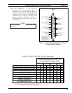
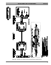
Normally, a pre-wired 100-foot (30.5 meters) cable is
supplied with the console equipment package for RS-422
control data interconnections between the CEC/IMC and a
co-located C3 Maestro console. The cable's part number is
19B804083P3. It has a female DB-25 connector on one end
for mating to the RS-422 male DB-25 connector at the PC.
The other end is "pig-tailed" (not terminated) so the cable's
24-gauge solid wires can be punched down to the correct
terminals at the required CEC/IMC punch block.
If using the supplied control data cable, mate its
female DB-25 to the PC's RS-422 male DB-25
connector, route it to the CEC/IMC, shorten the
cable as required, and punch the wires to the
correct terminals. See Table 4 or the cable's
assembly diagram near the end of this manual for
wire color coding.
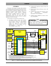
Also see Figure 6A and the
cable’s assemble diagram on page 36.
1
Add ten (10) to jumper numbers for earlier 3PXOCC1A
boards (JP2 thru JP5 = JP12 thru JP15).
2
Add ten (10) to jumper numbers for earlier 3PXOCC1A
boards (JP6 thru JP7 = JP16 thru JP17).