


INTERCONNECTING THE EQUIPMENT LBI-39101
21
Relay Outputs (if used)
Form-C relay contacts (single-pole double-throw) are
available from the Enhanced Audio Enclosure for external
device control. Contact connections are made at the screw-
terminal type terminal block on the rear panel labeled
"RELAYS". Even though these relays are also controlled
from the console’s dispatch keyboard, they are not the same
as and they should not be confused with the relays within the
CEC/IMC utilized for auxiliary I/O interfacing.
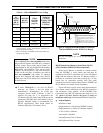
As shown in Table 25, the first relay (relay 1) is
activated when the console is keyed (PTTed). During the
key, the relay's common and normally-open contacts close
and its common and normally-closed contacts open. The
second relay's (relay 2) common and normally-open contacts
close while <Alt><F10> is depressed at the Dispatch
Keyboard. Like the first relay, this relay's action is
considered "momentarily" as it is only in the active state
when the <Alt><F10> keys are depressed. The third relay's
(relay 3) contacts toggle open/close at an <Alt><F9>
keystroke from the Dispatch Keyboard. The other relays are
not supported by software.
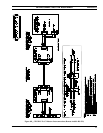
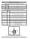
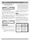
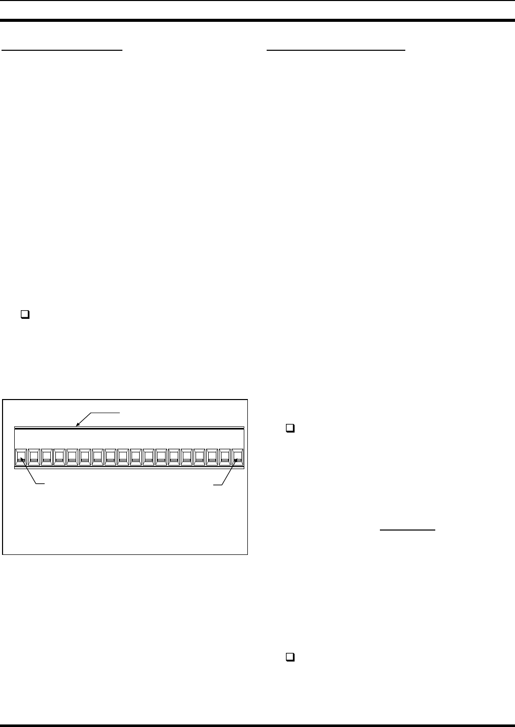
As required, connect the relay contact outputs to
external equipment. See Table 25 and Figure 9.
Specified contact rating for all relays is 0.75 amps
at 26 Vdc. Open contact isolation is specified to
500 Vrms at 60 Hz. Isolation between any relay
terminal and the Enhanced Audio Enclosure's
ground is also specified to 500 Vrms at 60 Hz.
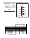
RELAYS
18
1
WIRE SECURING SCREWS
LOCATED ON TOP
WIRE ATTACHMENT:
1. UNPLUG TERMINAL BLOCK FROM MATING CONNECTOR.
2. IF REQUIRED, COMPLETELY LOOSEN WIRE SECURING SCREW.
3. INSERT WIRE.
4. TIGHTEN WIRE SECURING SCREW.
5. REPEAT FOR OTHER WIRES.
6. RECONNECT TERMINAL BLOCK TO "RELAYS" MATING CONNECTOR.
RELAY OUTPUT
TERMINAL 1
RELAY OUTPUT
TERMINAL 18
(See Table 25 for terminal identifications)
Figure 9 – Relay Terminal Block At
Enhanced Audio Enclosure
Call Director (if equipped)
As shown in Figure 1, all C3 Maestro-to-Call Director
interconnections at the console are made at the Enhanced
Audio Enclosure's connector labeled "CALL DIR". A Call
Director telephone patch also requires an additional 4-wire
balanced line between the Enhanced Audio Enclosure and
the console’s CIM within the CEC/IMC. At the CEC/IMC,
CIM audio channel/line four (4) is used for Call Director
interfacing. CD control data interfacing is handled over the
existing RS-232/RS-422 serial control data interface
between the PC and the CEC/IMC. Therefore, no additional
control data link must be added to support Call Director
patch equipment. Refer to Figures 1, 5, 6 and 10 for
interconnection details and the following discussion on
CEC/IMC line audio line requirements.
Console-to-CEC/IMC Audio Interconnections
All CEC/IMC line audio in to and out of a C3 Maestro
dispatch console system enters and leaves via the DB-25
connector labeled "LINES 1 - 4" on the Enhanced Audio
Enclosure's rear panel. If the console is connected to a Call
Director, Line 4 between the Enhanced Audio Enclosure and
the CEC/IMC must be established for CD audio routing
between the console and the CEC/IMC. In this case, the
third unselect speaker audio is not available.
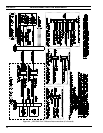
Table 7 describes the audio signals between the
Enhanced Audio Enclosure and the CIM within the
CEC/IMC. The descriptions are relative to the Enhanced
Audio Enclosure. All signals on these 600-ohm pairs have
typical levels between -5 dBm to 0 dBm.
If not accomplished in the previous instructions in
this manual, install a 4-wire balanced line (two
pairs) between the required CEC/IMC Audio
Concentrator Card and Enhanced Audio Enclosure.
Refer to the section entitled "
CEC/IMC
INTERCONNECTIONS
" for details (page 11). In
most cases, the pre-wired 100-foot audio cable
(part number 19B804083P2) is utilized as
described in the "
Audio Links
" subsection (page
14).
Console-to-Call Director Interconnections
Table 8 describes the various signals between the
Enhanced Audio Enclosure and the Call Director. The
descriptions are relative to the Enhanced Audio Enclosure.
All Enhanced Audio Enclosure connections are made at the
"CALL DIR" female DB-9 connector. Figure 10 and Table
13 indicate the connector's pin-out.
Interconnect the Enhanced Audio Enclosure to the
Call Director as required per Tables 8 and 13,
Figure 10, and the Call Director's documentation.