


LBI-39101 INTERCONNECTING THE EQUIPMENT
22
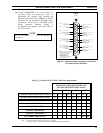
Table 7 −− Enhanced Audio Enclosure-To-CEC/IMC Call Director Audio Signal Descriptions
TYPE
INPUT /
OUTPUT
USE
Patched Radio Input Radio audio from CIM TX channel/line 4. During a CD telephone patch, this audio is heard
at the telephone.
CD/Operator Mic Output Telephone/operator mic audio to CIM RX channel/line 4. This audio is heard at the radio.
Table 8 −− Enhanced Audio Enclosure-To-Call Director Control & Audio Signal Descriptions
NAME
INPUT /
OUTPUT
USE
ON-HOOK N.O.
(pin 1) and
ON-HOOK COMMON
(pin 6)
Output
Optional – Normally-open relay contact (Form-A). Closure generated when the
console disconnects the CD from the CEC/IMC. Used to put CD on-hook, if an input
exists. The relay remains energized for approximately 1.2 seconds. This value is
fixed in the firmware and cannot be changed. Relay contact rating:
0.75 A @ 26 Vdc, 500 Vrms isolation from ground @ 60 Hz
CD HOOK SENSE IN
(pin 2) *
Input
Active low when the CD is placed off-hook. Typically connects to a dry contact
(SPST switch, Form-A relay, etc.) from Call Director.
CD JACK SENSE IN
(pin 3) *
Input
Optional – Active low when a handset is plugged into the CD. This handset overrides
all audio connections to the Enhanced Audio Enclosure. The operator talks directly
to the phone via the handset instead of using the console’s headset or mic/speaker.
Typically connects to a dry contact from Call Director.
GROUND (pin 4) * n/a Signal ground for CD HOOK SENSE IN and CD JACK SENSE IN sense inputs.
CD IN
(pins 5 and 9)
Input
Audio from the CD (telephone mic). This audio is heard by a radio in patch
operation, or by operator headset in normal operation. 600-ohm balanced input:
-26 dBm to -14 dBm, typically -20 dBm.
CD OUT
( pins 7 and 8)
Output
Radio/operator mic audio to the CD (telephone receiver). This audio is heard by the
telephone. 600-ohm balanced output:
-11 dBm to +1 dBm, typically -5 dBm.
* GROUND (pin 4) is common for CD HOOK SENSE IN (pin 2) and CD JACK SENSE IN (pin 3)
This ground
is not
isolated from chassis ground.
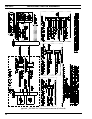
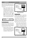
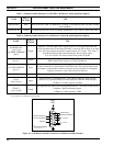
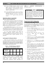
1
2
6
3
4
5
7
8
9
CD IN
CALL
DIR
NOTE:
1. VIEWED FROM BACK OF ENHANCED
AUDIO ENCLOSURE OR WIRING SIDE
OF MATING CONNECTOR.
HI/+
LO/-
CD OUT
HI/+
LO/-
ON-HOOK N.O.
ON-HOOK COMMON
CD HOOK SENSE IN
CD JACK SENSE IN
GROUND
Figure 10 −− Call Director Interface Connector At Enhanced Audio Enclosure