


AUDIO TOWER REPLACEMENT LBI-39101
23
EQUIPMENT ROOM GROUNDING
Proper grounding techniques should be observed in
order to protect the equipment and service personnel from
lightning and other sources of electrical surges. All consoles
should be connected to properly grounded 3-terminal
outlets. If used, lightning arrestors, UPS equipment, and all
other console-associated equipment should also be properly
grounded. If necessary, refer to LBI-39067 for detailed
grounding procedures.
AC POWER AND UPS EQUIPMENT
All consoles require 115 or 230 Vac (47 to 63 Hz)
power sources. As a minimum, each outlet should be circuit-
breaker protected per local building codes.
UPS protection is optional. Maximum required UPS
wattage rating for a single console system should be based
on the required maximum sums of the Enhanced Audio
Enclosure (200 watts max.), the PC's computer (per
manufacturer's specifications) and the PC's video display
monitor (per manufacturer's specifications).
AUDIO TOWER REPLACEMENT
This section lists the steps necessary to replace earlier
Audio Tower hardware with Enhanced Audio Enclosure
hardware. Existing Personal Computer (PC) hardware is not
replaced, only the C3 Maestro application software which it
executes. To avoid duplication of information, many
references are made to other Enhanced Audio Enclosure-
related installation and set-up sections within this manual.
NOTE
If installing a completely new C3 Maestro console
system (new PC and new Enhanced Audio
Enclosure equipment), disregard this section
entirely and proceed to the "
POWER-UP
PROCEDURE
" on page 25.
1. Power-Down and Cable Disconnections
REMOVE AC POWER from the PC system.
REMOVE AC POWER from the Audio Tower
system.
Disconnect the Dispatch Keyboard from the Logic
Board installed in the PC. If a new keyboard (with
DB-9 connector) is supplied, this old keyboard is
no longer needed.
Disconnect the large PC-to-Audio Tower
interconnect cable connecting the Audio Tower to
the Logic Board installed in the PC. This cable is
no longer needed.
At the Audio Tower, label and then disconnect all
cabling between it and external equipment and
accessories. Equipment and accessories includes
items such as the Volume Controller Box,
microphones, speakers, headset jack boxes, audio
lines to and from the CEC/IMC, pager, recorder(s),
Call Director, etc.
Remove the Audio Tower, Volume Controller Box,
speakers and related cabling. These items are no
longer needed.
2. Logic Board Removal
Review the procedures in the documentation
included with the PC relating to expansion board
installation/removal.
Remove the PC's outside cover in accordance with
the manufacture's instructions.
Identify and remove the Logic Board installed in
one of the PC's expansion slots. The large PC-to-
Audio Tower interconnect cable (disconnected in
step 1) mated with this board's DB-37 connector.
The Dispatch Keyboard's small round DIN
connector also mated to a connector on this board.
Using the screw which held the Logic Board in
place, install a blank expansion slot cover (not
supplied). Installation of this cover will prevent
dust and other foreign matter from entering the PC.
Replace the PC's outside cover.
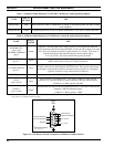
3. PC-To-Enhanced Audio Enclosure Serial Link
Using PC's CMOS set-up program, enable the PC's
serial port (DB-9 connector) for COM2/address
2F8h and interrupt IRQ3 operation. If the PC is
equipped with two serial ports, enable the second
port (typically port "B"). The C3 Maestro's
application software sets the port's baud rate. Refer
to the section entitled "
SOFTWARE
INSTALLATION AND SET-UP
PROCEDURE
", subsection "
PC CMOS SET-UP
PROGRAM
" (page 26) for additional information.
Connect this serial port (COM2) to the Enhanced
Audio Enclosure in accordance with subsection
"
PC-To-Enhanced Audio Enclosure Serial Data
Interconnect Cable
" in this manual (page 18).
NOTE