


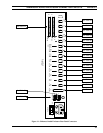

ENHANCED AUDIO ENCLOSURE CONNECTOR PIN-OUTS LBI-39101
35
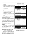
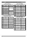
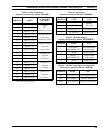
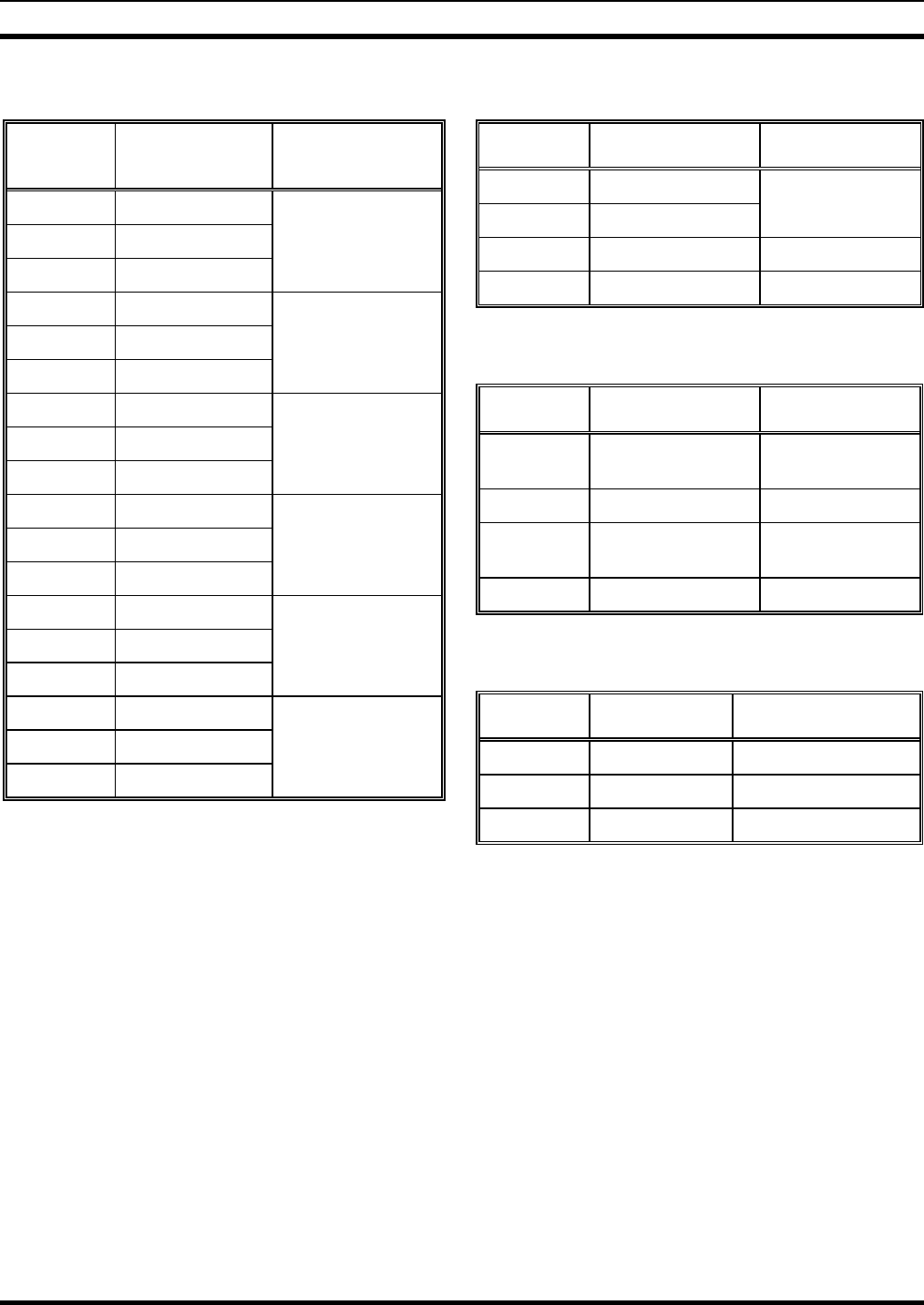
Table 25 – Relay Connections
(18-position terminal block labeled "RELAYS")
TERMINAL NAME*
ACTIVATION
METHOD
1 RELAY_1_NO
console
2 RELAY_1_C PTT
3 RELAY_1_NC
(momentary action)
4 RELAY_2_NO
Dispatch Keyboard
5 RELAY_2_C <Alt><F10>
6 RELAY_2_NC
(momentary action)
7 RELAY_3_NO
Dispatch Keyboard
8 RELAY_3_C <Alt><F9>
9 RELAY_3_NC
(toggle action)
10 RELAY_4_NO
(currently not
11 RELAY_4_C supported
12 RELAY_4_NC
by software)
13 RELAY_5_NO
(currently not
14 RELAY_5_C supported
15 RELAY_5_NC
by software)
16 RELAY_6_NO
(currently not
17 RELAY_6_C supported
18 RELAY_6_NC
by software)
* "NO" = normally-open contact; "C" = common contact;
"NC" = normally-closed contact.
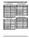
Table 26 – Pager Input
(4-position terminal block labeled "PAGING")
TERMINAL NAME USE
1 PAGER_IN+
balanced
2 PAGER_IN-
audio input
3 PAGER_PTT_IN PTT (enable) input
4 PS_GND_IN ground for pin 3
Table 27 – Recorder Outputs
(4-position terminal block labeled "RECORDER")
TERMINAL NAME USE
1
USEL/TELE_
RECORDER_OUT
unselect/telephone
recorder output
2 AGND ground for pin 1
3
SELECT_
RECORDER_OUT
select recorder
audio output
4 AGND ground for pin 3
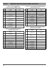
Table 28 – Auxiliary Audio Inputs (Not Supported)
(1/8-inch stereo phone jack labeled "AUX. IN")
TERMINAL NAME USE
tip AUX_LEFT_IN left chn. input (green)
ring AUX_RIGHT_IN right chn. input (red)
sleeve AUX_IN_GND grounds T and R (black)