


LBI-39101 INTERCONNECTING THE EQUIPMENT
14
2-Wire/4-Wire = 4 Wire
TX Level = (as required; use -15 dBm if line loss is 0 dB)
Dial Backup = Manual
Loop Back Time = 15 minutes
Dial Line = RJ11
Line Current Disconnect = Long
Long Space Disconnect = Enabled
V.22 Guard Tone = Disabled
• •
MNP Options
MNP Protocol = Enabled
Auto Fallback = Enabled (or Normal)
Flow Control = CTS Only
XON/XOFF Pass Through = Enabled
Data Compression = Disabled
Inactivity Timer = Off
Break Control = 5
• •
DTE Options
Synchronous/Asynchronous Data = Asynchronous
DTE Rate = 9600
Character Length = 8 Bits
Parity = None
Commanded Dialer = Asynchronous
AT Command Set = Disabled
DTR Control = Disabled
DSR = Forced High
DCD = Normal
CTS = Forced High
DTE Fallback = Disabled
Options = Retained At Disconnect
• •
Test Options - All Disabled (or factory defaults)
• •
Dial Line Options - (not applicable; leave at factory
defaults)
• •
Speaker Options
Volume Control = Low
Control = On Until Carrier Detect
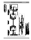
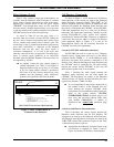
Audio Links
Audio Concentrator Cards at the back of the CEC/IMC
cabinet provide audio connections at the CEC/IMC. Like the
control data connections, audio connections are normally
extended out of the CEC/IMC cabinet via Telco cable(s) and
line terminations are actually made at punch blocks. See
Figure 6A. See the customer-specific system documentation
print-outs for Concentrator Card connector pin-out details.
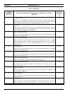
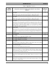
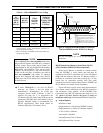
Table 5 shows line requirements between the C3
Maestro and the CEC/IMC for each audio input or output 2-
wire 600-ohm twisted pair. Note that two (2) Enhanced
Audio Enclosure output pairs, Line 2 out and Line 3 out are
never used. These audio output lines are provided for future
expansion use.
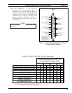
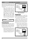
At the C3 Maestro, audio connections terminate at the
DB-25 connector on the Enhanced Audio Enclosure's rear
panel. This connector is labeled "LINES 1-4". Its pin-out is
shown in Figures 5 and 6A and Table 12. It has female
contacts; therefore, the required mating connector is a male
DB-25.
Normally, a pre-wired 100-foot (30.5 meters) cable is
supplied with the console equipment package for audio
interconnections between the Enhanced Audio Enclosure
and the CEC/IMC. This 8-pair shielded cable's part number
is 19B804083P2. It has a male DB-25 connector on one end
for mating to the Enhanced Audio Enclosure's "LINES 1-4"
female DB-25 connector. The other end is "pig-tailed" (not
terminated) so the cable's 24-guage solid wires can be
punched down to the correct terminals at the required
CEC/IMC's punch block.
If cable 19B804083P2 is used, mate its DB-25 to
the Enhanced Audio Enclosure, route it to the
CEC/IMC, shorten it as required, and punch the
wires to the correct punch block's terminals. Wire
color coding is indicated in Figure 5 and in the
cable's assembly diagram shown at the end of this
manual (page 37). Refer to the CEC/IMC
customer-specific system documentation print-outs
for CEC/IMC Audio Concentrator Card pin-outs
which map over to the punch blocks via Telco
cables.