


LBI-39101 INTERCONNECTING THE EQUIPMENT
20
assembled with one amplified speaker in the far left-hand
position (select speaker), one amplified speaker in the far
right-hand position (unselect speaker) and blank panels
installed in the two center positions. Four-speaker consoles
are generally equipped with two separate 2-speaker rack
mount assemblies.
Install or mount each Speaker Assembly in a
suitable location and then interconnect it to the
Enhanced Audio Enclosure using cable
P29/5010150000 (350A1371P29). This cable is
9 feet (2.74 meters) in length. It is identical to the
cable that interconnects the PC's serial COM port
to the Enhanced Audio Enclosure. Mate the cable's
female DB-9 connector to the appropriate male
DB-9 connector on the Enhanced Audio
Enclosure's rear panel. These male connectors are
labeled "SEL SPKR" (select speaker), "UNSEL
SPKR1" (first unselect speaker), "UNSEL
SPKR2" (second unselect speaker) and "UNSEL
SPKR3" (third unselect speaker). Connect the
other end of the cable to the female DB-9
connector at the respective Speaker Assembly. If
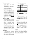
necessary, see Tables 18 and 19 for DB-9 pin-outs.
Load resistors are not required for unused
Enhanced Audio Enclosure speaker outputs.
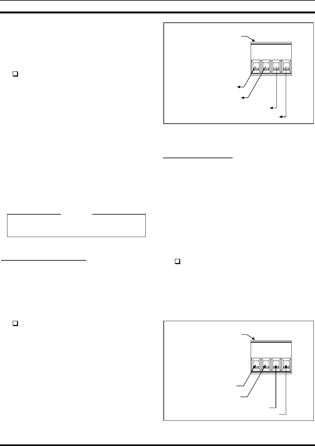
Recorder Outputs (if used)
To provide call-check recorder support, select and
unselect audio outputs are available from the Enhanced
Audio Enclosure. The unselect output may, however, be
reconfigured via software to output Call Director audio.
These unbalanced 600-ohm outputs appear at the removable
screw-terminal type terminal block labeled "RECORDER"
on the Enhanced Audio Enclosure's rear panel.
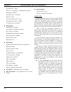
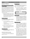
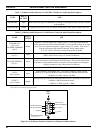
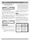
Interconnect the outputs to call-check recorders as
required. These outputs are not isolated from
ground through isolation transformers and the two
ground terminals are common. See Figure 7 and
Table 27 for terminal identification. See the
specifications in LBI-39100 for audio signal output
level specifications. If required, audio output levels
may be adjusted via a C3 Maestro note card.
RECORDER
41
WIRE SECURING SCREWS
LOCATED ON TOP
WIRE ATTACHMENT:
1. UNPLUG TERMINAL BLOCK FROM
MATING CONNECTOR.
2. IF REQUIRED, COMPLETELY
LOOSEN WIRE SECURING SCREW.
3. INSERT WIRE.
4. TIGHTEN WIRE SECURING SCREW.
5. REPEAT FOR OTHER WIRES.
6. RECONNECT TERMINAL BLOCK TO
"RECORDER" MATING CONNECTOR.
GROUND
UNSELECT/
TELEPHONE OUT
SELECT OUT
GROUND
Figure 7 – Recorder Outputs At
Enhanced Audio Enclosure
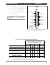
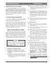
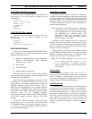
Paging Input (if used)
Paging connections are located on a second removable
screw-terminal terminal block on Enhanced Audio
Enclosure's rear panel. A 600-ohm balanced line audio input
and a PTT (page enable) input are included. As shown in
Figure 8, this terminal block is labeled "PAGING".
Pager balanced audio on terminals 1 and 2 is switched
in when the PTT line at terminal 3 becomes active by
grounding it to terminal 4. Typically, the PTT action is
accomplished by a relay in the pager. During a page, no
other audio signals are applied to the Line 1 output. Also,
the paging signal is sent to the headsets and speakers
approximately 16 dB lower than other audio signal levels.
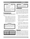
Connect the pager to the terminal block in
accordance with the manufacturer's instructions,
Figure 8 and Table 26. The audio terminals are
isolated from ground. See the specifications page in
LBI-39100 for audio signal input level
specifications. If required, audio input level
adjustment may be accomplished via a C3 Maestro
note card.
PAGING
41
WIRE SECURING SCREWS
LOCATED ON TOP
WIRE ATTACHMENT:
1. UNPLUG TERMINAL BLOCK FROM
MATING CONNECTOR.
2. IF REQUIRED, COMPLETELY
LOOSEN WIRE SECURING SCREW.
3. INSERT WIRE.
4. TIGHTEN WIRE SECURING SCREW.
5. REPEAT FOR OTHER WIRES.
6. RECONNECT TERMINAL BLOCK TO
"PAGING" MATING CONNECTOR.
PAGER AUDIO
INPUT -
PAGER AUDIO
INPUT +
PAGER PTT INPUT
GROUND
Figure 8 – Pager Inputs At Enhanced Audio Enclosure
NOTE