


INTERCONNECTING THE EQUIPMENT LBI-39101
13
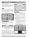
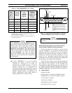
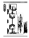
Table 4 – Cable 19B804083P3 Color Coding
PC
RS-422
PORT
DB-25
PIN NO.
CONSOLE
RS-422
SIGNAL
WIRE
COLOR
(Also see
page 36)
TYPICAL
CEC/IMC
CONNECTION
IDENTIFI-
CATION *
1 cable shield n/a none **
2 TX- white/blue
CRT
01 RX-
DATA
14 TX+ blue
CRT
01 RX+
DATA
3 RX- white/orange
CRT
01 TX-
DATA
16 RX+ orange
CRT
01 TX+
DATA
7 ground white/green none **
* CEC/IMC Data Concentrator Card identification. See
customer-specific system documentation print-outs for
specific pin/terminal numbers.
**Wire not terminated at CEC/IMC punch block. Insulate and
tie back at punch block.
Cable 19B804083P3 is not compatible with earlier
plug-in RS-422 boards used with the C3 Maestro
console system. These earlier plug-in boards are
manufactured by ICS and included model numbers
RS422AT-P and RS422I-P. They can be easily
identified by the presence of two LED indicators
visible on the rear plate. In addition, the cable is
also not compatible with earlier C3 Maestro
console PCs equipped with main board RS-422
COM ports such as the Dasher PCs manufactured
by Data General.
If cable 19B802083P3 is not used for RS-422
hook-ups, see Figures 4 and 6A and/or the
manufacturer's documentation for COM port
connector pin-out details. Fabricate a cable as
required and then use it to interconnect the
C3 Maestro's RS-422 control data COM port to the
appropriate CEC/IMC Data Concentrator Card as
required. Shielded cabling is recommended. Per
RS-422 specifications, cable length should be
limited to 4000 feet (1219 meters) or less.
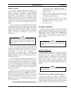
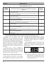
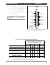
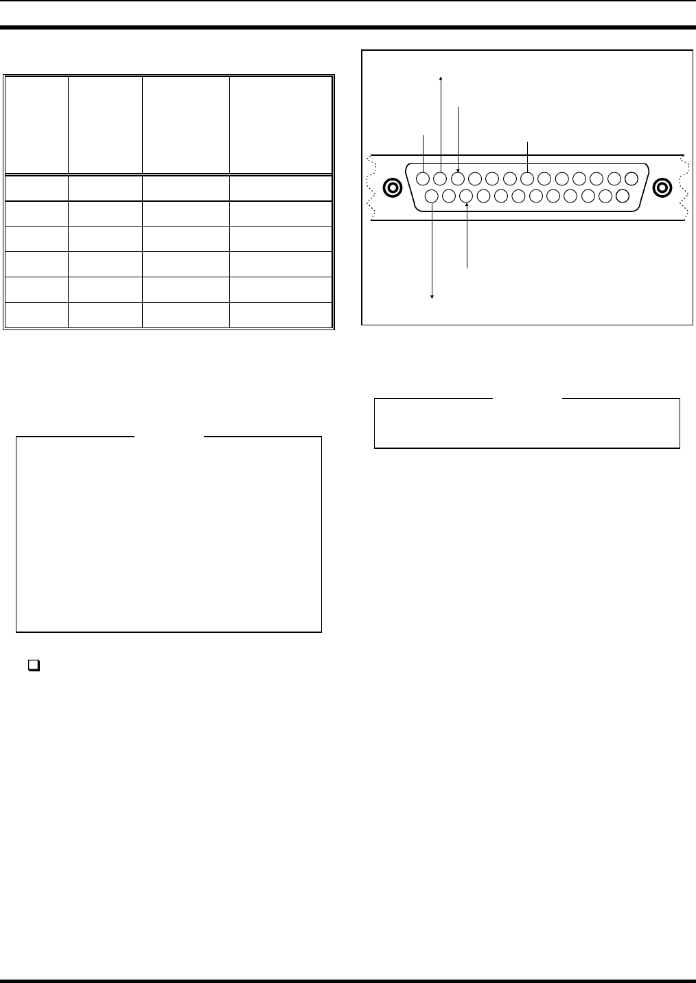
NOTES:
1. VIEWED FROM BACK OF COMPUTER (MALE DB-25) OR
WIRING SIDE OF MATING CONNECTOR (FEMALE
DB-25).
2. TX LINES MUST CONNECT TO "CRT" RX LINES AT
CEC/IMC CONCENTRATOR CARD OR PUNCH BLOCK, +
TO + AND - TO -.
RX LINES MUST CONNECT TO "CRT" TX LINES AT
CEC/IMC CONCENTRATOR CARD OR PUNCH BLOCK, +
TO + AND - TO -.
3. COLOR CODING INDICATES CABLE 19B804083P3 WIRE
COLORS.
13121110
25
9876
54321
14
24232221
15
201918
1716
RS-422 RX-
(WHITE/ORANGE)
RS-422 RX+
(ORANGE)
RS-422 TX-
(WHITE/BLUE)
RS-422 TX+
(BLUE)
SIGNAL GROUND
(WHITE/GREEN)
SHIELD
Figure 4 – Plug-In RS-422 Board DB-25 Connector
Pin-Out (B&B Electronics 3PXOCC1A Board)
Do not over-tighten the screws on the DB-style
connectors.
RS-232 Interfacing (Remote Console Hook-Ups Via
4-Wire Modems And RS-232 Interconnections)
When the C3 Maestro is installed at a remote location
from the CEC/IMC, a serial control data link must be
established via RS-232 connections and 4-wire full-duplex
9600 baud data modems. Since the C3 Maestro requires a
dedicated or continuous serial link (non-dial-up), a 4-wire
leased line (or equivalent) meeting 3002 data grade
specifications must be employed between the CEC/IMC and
the C3 Maestro in a remote console installation.
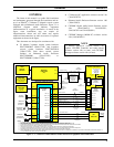
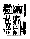
Figure 6B shows typical control data interconnections
for a remote console installation using RS-232 connections
and full-duplex 4-wire modems. At the CEC/IMC Data
Concentrator Card, RS-232 connections are made at J13, not
J12. Observe all notes listed in the figure if wiring an
installation of this type. Recommended modem settings are:
• •
Modem Options
DCE Rate = 9600
Originate/Answer = Originate (CEC/IMC modem)
Originate/Answer = Answer (C3 Maestro modem)
V.32 Fast Train = Enabled
Auto Retrain = Enabled
Internal/External Clock = Internal
Dial-Up/Leased Line = Leased
NOTE
NOTE