


LBI-39101 AUDIO TOWER REPLACEMENT
24
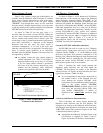
4. Application Software Installation
If necessary, obtain C3 Maestro application
software V5.0 (or later).
Install this software on PC's hard disk drive in
accordance with the supplied instructions.
Optional: Delete the old C3 Maestro application
software from the PC's hard disk drive.
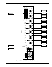
5. Console-To-CIM Serial Control Data Link
Normally, no console-to-CIM serial link changes
are necessary. However, if upgrading/replacing the
plug-in RS-422 board installed in one of the PC's
expansion slots (for improved static protection), the
DB-25 connector which plugs to this board will, in
most cases, require rewiring. Older RS-422 boards
have different pin-outs from the newer boards.
Refer to the plug-in boards' documentation and/or
LBI-39055 for pin-out information. Also see the
subsection in this manual entitled "Control Data
Link" (begins on page 12) and Figure 6 in this
manual.
6. Console-To-CIM Audio Link
If using existing modular cabling, cut the modular
plugs off modular cables. Maintain connections to
the CEC/IMC Audio Concentrator Card or punch
blocks. Next, wire these audio lines to a male
DB-25 connector (not supplied) and mate the
connector to the Enhanced Audio Enclosure's
"LINES 1-4" female DB-25 connector. See the
subsection in this manual entitled "Audio Links"
(begins on page 14) for additional information.
If using the pre-wired 100-foot audio cable,
remove the existing modular cabling connections
from the CEC/IMC Audio Concentrator Cards or
punch blocks. Next, wire the 100-foot audio cable
to the CEC/IMC Audio Concentrator Card/punch
block in accordance with the subsection in this
manual entitled "Audio Links" (begins on page
14).
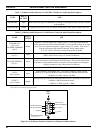
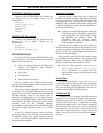
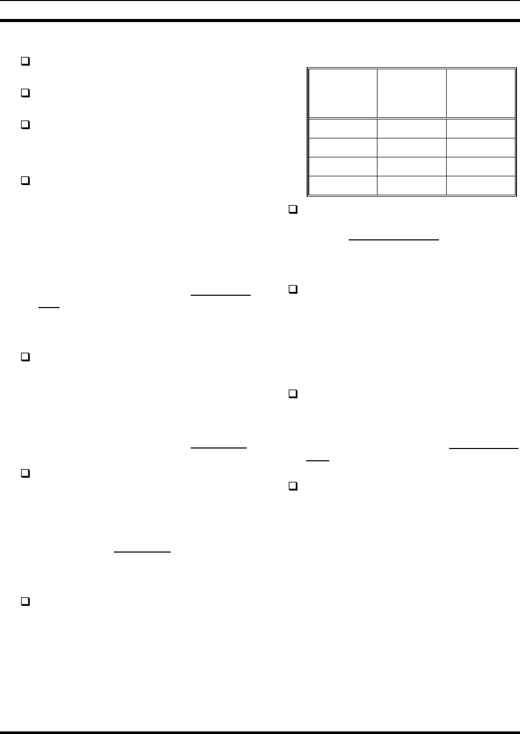
7. Dispatch Keyboard
The existing (old) Dispatch Keyboard was
disconnected in step 1. If a new Dispatch Keyboard
(with male DB-9 connector) is not supplied and this
keyboard must be utilized, replace its small round
DIN connector with a DB-9 connector (not
supplied) in accordance with the following table.
Also see Table 24:
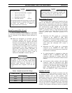
Table 9 – Dispatch Keyboard Cable
Color Coding
MALE
DB-9 PIN
NUMBER
CABLE
WIRE
COLOR
USE
1 red dc power
2 white keyboard data
4 green ground
6 (bare) shield
Connect the Dispatch Keyboard to the Enhanced
Audio Enclosure in accordance with subsection
entitled "Dispatch Keyboard" in this manual
(page 18).
8. Microphones & Headsets
Connect existing mics and headset jack boxes to
the Enhanced Audio Enclosure per section
"INTERCONNECTING THE EQUIPMENT",
subsection "ENHANCED AUDIO
ENCLOSURE" in this manual (begins on page
18). No wiring changes are necessary.
9. Footswitches
Audio Tower "FOOTSWITCH 1" should now be
used as an operator footswitch. Connect it to
Enhanced Audio Enclosure's "OPER FT. SW."
connector. This footswitch keys all non-supervisory
mics. See the subsection entitled "Footswitches (if
used)" in this manual (page 19) for additional
details.
Audio Tower "FOOTSWITCH 2" should now be
used as a supervisor footswitch. Connect it to
Enhanced Audio Enclosure's "SUPER FT. SW."
connector. This footswitch keys only the
supervisor's headset.
10. Speakers
Speakers used with the Audio Tower are un-amplified
units; therefore, they cannot be used with the Enhanced
Audio Enclosure. Speakers used with the Enhanced Audio
Enclosure are amplified units and each includes a volume
control. The Volume Controller Box is not employed in
Enhanced Audio Enclosure applications.