


INTERCONNECTING THE EQUIPMENT LBI-39101
19
Microphone priority is (highest to lowest):
• Supervisory Headset Mic (highest)
• Operator Headset Mic
• Boom/Gooseneck Mic
• Desk Mic (lowest) (lowest)
The boom/gooseneck mic has priority over the desk
mic when no headset is connected. Desk mic audio
and PTTs are ignored if a headset or
boom/gooseneck mic is connected.
Boom/Gooseneck Mic (if used)
A boom microphone (option CRMC3E or equivalent)
or a gooseneck microphone (option CRMC3F or equivalent)
may be connected to the Enhanced Audio Enclosure as
follows:
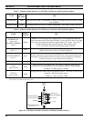
Mount the microphone in accordance with the
instructions supplied with the mic. With the
gooseneck microphone, the supplied male DB-9
connector must be soldered to the cable's wires in
accordance with Table 6 after the mic's cable is
routed through the mounting surface. Connect the
boom/gooseneck male DB-9 connector to the
female DB-9 connector labeled "B/G MIC" on
Enhanced Audio Enclosure's rear panel. Cable
length is four (4) feet (1.22 meters). Table 14
indicates the "B/G MIC" connector's pin-out.
DO NOT
connect a boom or gooseneck
microphone to one of the other female DB-9
microphone connectors at the rear panel of the
Enhanced Audio Enclosure. Damage to the
boom/gooseneck mic's magnetic voice coil may
occur.
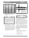
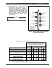
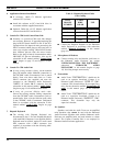
Table 6
−−
Boom/Gooseneck Mic Wiring*
WIRE COLOR DB-9 PIN NUMBER
Black 9
White 5
Shield 1
* Also see the following
NOTE
.
All boom and gooseneck mic connectors (male DB-
9) must have pins 2 and 3 jumpered together so the
sense circuit will be active when the mic is
connected to the Enhanced Audio Enclosure.
Footswitches (if used)
Two (2) female DB-9 connectors are located on the rear
panel of the Enhanced Audio Enclosure for footswitch
interconnections. Footswitches used with the C3 Maestro
dispatch console include single-footswitch option CRSU3B
and dual-footswitch option CRSU3C. On the dual-
footswitch, one switch (PTT) keys the mic and the other
switch is a monitor switch. A single-footswitch provides
only a PTT function. See Tables 20 and 21 for specific
connector pin-out details. Footswitch operation is as
follows:
•
Depressing the PTT switch on a footswitch
connected to the "OPER FT. SW." DB-9
connector will activate the operator's headset mic if
the headset is connected. If the headset is not
connected, the boom or gooseneck mic will become
active when this footswitch PTT switch is
depressed.
•
Depressing the PTT switch on a footswitch
connected to the "SUPER FT. SW." DB-9
connector will activate the supervisor's headset mic
if the headset is connected.
•
If a dual footswitch is connected to either the
"OPER FT. SW." or "SUPER FT. SW." DB-9
connectors, depressing its monitor switch will
activate the console's conventional channel monitor
function.
All footswitch cables terminate with male DB-9
connectors. Mate the appropriate male DB-9
footswitch connector to the respective female DB-9
connector at the Enhanced Audio Enclosure's rear
panel. Tables 20 and 21 indicate "OPER FT.
SW." and "SUPER FT. SW." connector pin-outs.
Speakers (if used)
Desktop and rack-mount Speaker Assemblies used with
the Enhanced Audio Enclosure each basically consist of
mechanical hardware, one or more speakers, audio
amplification circuitry, and a volume control potentiometer.
The mechanical hardware may be of several different
varieties providing either desktop speaker operation in the
form of a self-contained single-speaker case or a rack-mount
version in the form of a standard 19-inch EIA rack mount
assembly. The 2-speaker rack-mount versions are generally
NOTE
CAUTION!
NOTE