


7
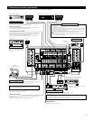
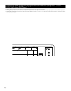
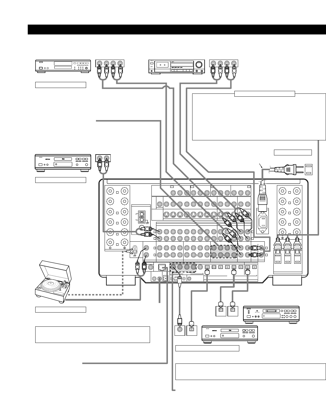
Connecting the audio components
• When making connections, also refer to the operating instructions of the other components.
SPEAKER SYSTEMS
ANTENNA TERMINALS
MULTI
ZONE 2
SURR.-B
SURR.-A
CENTER
CONPONENT VIDEO
FRONT
SURR.
BACK
R
R
R
R
R
R
L
R
L
R
L
R
L
SPEAKER SYSTEMS
SPEAKER IMPEDANCE
FRONT, CENTER, SURR. BACK
MULTI ZONE 2
SURROUND A OR B / 6 16Ω
A + B / 8 16Ω
/ 6 16Ω
AC OUTLETS
SWITCHED TOTAL 120W (1A.) MAX.
AC 120V 60Hz
MULTI
ZONE 2
SURR.-B
SURR.-A
FRONT
SURR.
BACK
L
L
L
L
L
IN
DVD
Y
VDP TV DBS /
V. AUX VCR-1 VCR-2 VCR-3 VCR-1 VCR-2 VCR-3
12SAT1
VIDEO
S-VIDEO
OUT
OUT OUT
IN
IN
IN
EXT. IN-1
SW
12
EXT. IN
(REMOTE CONTROL)
ROOM TO ROOM
DENON
LINK
POWER AMP
RS-232C
TRIGGER OUT
DC 12V 20mA MAX.
OPTICAL
DIGITAL
345
12345656
EXT. IN-2 PRE OUT OUT
PREOUT
OUT
OUT
IN OUT
AUDIO
IN
MONITOR
DVD
VDP TV
DBS /
V. AUX VCR-1 VCR-2 VCR-3 VCR-1 VCR-2 VCR-3
SAT
MD /
AC IN
TAPE-2
CDR /
TAPE-1
MD /
MULTI ZONE
TAPE-2 1 2
CDR /
TAPE-1
DVD
CENTER SURR.
SURR.
BACK
SURR.
BACK
SURR.
BACK
FRONT CENTER SURR.FRONT
DOLBY DIGITAL RF
CENTER SURR.FRONTPHONO
SIGNAL
GND
CD
MULTI ZONE
IN
TV
Y
IN
DBS / SAT
Y
OUT
MONITOR
P
B
/C
B
P
R
/C
R
P
B
/C
B
P
R
/C
R
P
B
/C
B
P
R
/C
R
P
B
/C
B
P
R
/C
R
Y
AM
LOOP
FMCOAX.
75Ω
ANT.
COAXIAL
CONTROL OUT
OUT
IN
IN
SW SW
R
OUTPUT
L
R
L
DIGITAL AUDIODIGITAL AUDIO
RLRL
OUTPUT INPUT
RLRL
RLRL
OUTPUT INPUT
RLRL
OUTPUT INPUT
OPTICALCOAXIAL
OUTPUT
OPTICAL
DIGITAL AUDIODIGITAL AUDIO
B
R
L
R
L
R
L
R
L
R
L
R
L
B
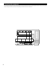
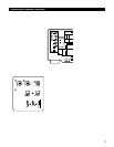
CD player
Connecting a CD player
Connect the CD player’s analog
output jacks (ANALOG OUTPUT) to
this unit’s CD jacks using pin plug
cords.
Connecting a turntable
Connect the turntable’s output cord to the AVR-5803’s PHONO jacks, the
L (left) plug to the L jack, the R (right) plug to the right jack.
NOTE:
This unit cannot be used with MC cartridges directly. Use a separate
head amplifier or step-up transformer.
If humming or other noise is generated when the ground wire is
connected, disconnect the ground wire.
Turntable
(MM cartridge)
Ground wire
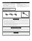
Extension jacks for future use
AC cord
(Supplied)
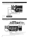
Connecting the pre-out jacks
Use these jacks if you wish to connect external power amplifier(s) to
increase the power of the front, center, surround and surround back sound
channels, or for connection to powered loudspeakers.
When using only one surround back speaker, connect it to left channel.
Connecting the AC OUTLETS
AC OUTLETS
• SWITCHED
(total capacity – 120 W (1 A.))
The power to these outlets is turned on and off in conjunction with the POWER
switch on the main unit, and when the power is switched between on and
standby from the remote control unit.
No power is supplied from these outlets when this unit’s power is at standby.
Never connect equipment whose total capacity is above 120 W (1 A.)
NOTE:
Only use the AC OUTLETS for audio equipment. Never use them for hair driers,
TVs or other electrical appliances.
AC outlets (wall)
AC 120V, 60Hz
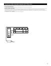
MD recorder, DAT deck or other component
equipped with digital input/output jacks
CD player or other component equipped
with digital output jacks
Connecting the DIGITAL jacks
Use these for connections to audio equipment with digital output.
Refer to page 29 for instructions on setting this terminal.
NOTES:
• Use 75 Ω/ohms cable pin cords for coaxial connections.
• Use optical cables for optical connections, removing the cap before connecting.
Connecting a tape deck
Connections for recording:
Connect the tape deck’s recording input jacks (LINE IN or REC) to this
unit’s tape recording (OUT) jacks using pin plug cords.
Connections for playback:
Connect the tape deck’s playback output jacks (LINE OUT or PB) to this
unit’s tape playback (IN) jacks using pin plug cords.
CD recorder or Tape deck 1 MD recorder or Tape deck 2
Denon Link terminal
Use this terminal to connect a Denon DVD player for high quality digital
multichannel sound.
For details, refer to the DVD player’s operating instructions.
DIGITAL EXT. IN
Extended function for future use.