


12
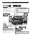
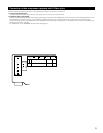
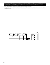
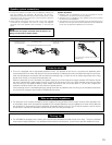
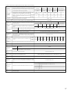
Connecting the external input (EXT. IN) jacks
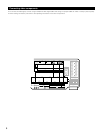
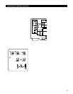
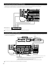
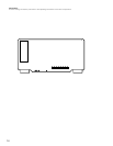
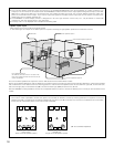
Connecting the MULTI ZONE jacks
• These jacks are for inputting multi-channel audio signals from an outboard decoder, or a component with a different type of multi-channel
decoder, such as a DVD Audio player, or a multi-channel SACD player, or other future multi-channel sound format decoder.
• When making connections, also refer to the operating instructions of the other components.
• If another pre-main (integrated) amplifier is connected, the multi-zone jacks can be used to play a different program source in another room at
the same time. (See pages 46, 47.)
SPEAKER SYSTEMS
ANTENNA TERMINALS
MULTI
ZONE 2
SURR.-B
SURR.-A
CENTER
SURR.
BACK
R
R
R
R
R
L
R
L
SAT1
VIDEO
S-VIDEO
OUT
OUT
IN
IN
IN
EXT. IN-1
SW
12
EXT. IN
(REMOTE CONTROL)
ROOM TO ROOM
DENON
LINK
POWER AMP
RS-232C
TRIGGER OUT
DC 12V 20mA MAX.
OPTICAL
DIGITAL
345
12345
EXT. IN-2 PRE OUT
IN OUT
AUDIO
VDP TV
DBS /
V. AUX VCR-1 VCR-2 VCR-3 VCR-1 VCR-2 VCR-3
SAT
DVD
CENTER SURR.
SURR.
BACK
SURR.
BACK
SURR.
BACK
FRONT CENTER SURR.FRONT
DOLBY DIGITAL RF
CENTER SURR.FRONTPHONO
SIGNAL
GND
CD
AM
LOOP
FMCOAX.
75Ω
ANT.
COAXIAL
CONTROL OUT
OUT
IN
IN
SW SW
R
L
R
L
R
L
Decoder with 8- or 6-
channel analog output
Front
Surround back
Surround
Subwoofer
Center
For instructions on playback using the external input (EXT. IN) jacks, see page 44.
SPEAKER SYSTEMS
MULTI
ZONE 2
SURR
.-
B
SURR.
BACK
R
R
R
R
L
R
L
R
L
R
L
SPEAKER SYSTEMS
SPEAKER IMPEDANCE
FRONT, CENTER, SURR. BACK
MULTI ZONE 2
SURROUND A OR B / 6 16Ω
A + B / 8 16Ω
/ 6 16Ω
AC OUTLETS
SWITCHED TOTAL 120W (1A.) MAX.
AC 120V 60Hz
MULTI
ZONE 2
BACK
L
L
IN
IN
EXT. IN-1
SW
12
EXT. IN
(REMOTE CONTROL)
ROOM TO ROOM
DENON
LINK
POWER AMP
RS-232C
TRIGGER OUT
DC 12V 20mA MAX.
OPTICAL
DIGITAL
345
12345656
EXT. IN-2 PRE OUT OUT
PREOUT
OUT
OUT
IN OUT
AUDIO
IN
VDP TV
DBS /
V. AUX VCR-1 VCR-2 VCR-3 VCR-1 VCR-2 VCR-3
SAT
MD /
TAPE-2
CDR /
TAPE-1
MD /
MULTI ZONE
TAPE-2 1 2
CDR /
TAPE-1
DVD
CENTER SURR.
SURR.
BACK
SURR.
BACK
SURR.
BACK
FRONT CENTER SURR.FRONT
DOLBY DIGITAL RF
CENTER SURR.FRONTPHONO
SIGNAL
GND
CD
FMCOAX.
75Ω
COAXIAL
CONTROL OUT
OUT
IN
IN
SW SW
L
R
++
OUTPUT
INPUT
AUX OUT
B
Another room
RC-616
INFRARED
RETRANSMITTER
Integrated pre-main amplifier
RC-617
INFRARED SENSOR
Extension jacks for future use.
For instructions on operations using the MULTI ZONE jacks, see page 43.
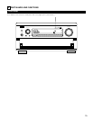
TRIGGER OUT
DC 12V turns on and off when the product’s power is turned on and off.
CONTROL terminal
Perform the following operation before using an external controller connected to the RS-232C terminal:
1. Press the ON/STANDBY button on the main unit and set the unit to the operating mode.
2. Perform the operation to turn off the power from the external control.
3. Check that the product has been set to the standby mode.
After checking the above, check the connections of the external controller. Operation is possible.