


48 of 80
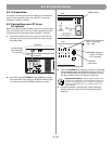
6.0 E4 System Setup
Input gain setup sequence
1. Set Opti-source
®
to Off. This allows you make the initial
gain setting.
2. Select the source Type and determine if Mic Power +12V is
needed. Set Mic Power to On if required. Leave it in the Off
setting if you are using line inputs.
3. Start your input source and monitor its signal on the gain
signal level meter. If the level is green, go to step 4. If the
level is yellow, increase the input gain until the level is green.
Likewise, if the level is red, reduce the input gain until the
level is green.
Programmer’s Note: You may have to repeat step 3 a
few times if the input source is a CD player. The output
level of a CD player varies based on the program material.
4. Set Opti-source to On. If you are using a source that
produces a varying output level due to program material,
such as a CD player, Opti-source leveling will compensate
for these variances. If your system will be switching among
multiple sources, Opti-source leveling will compensate for
variances among the different sources.
5. Repeat steps 1 to 4 for the remaining system inputs.
When you turn Opti-source on, you should only hear a small
change in volume. If you hear a large increase, raise the input
gain. Likewise, if you hear a large decrease, lower the input gain.
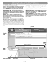
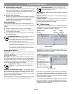
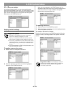
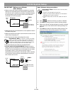
Input gain controls
Type – This setting determines the initial gain and amount of gain
available for the input signal. The following table lists the choices
for each input line.
Mic power +12V – This setting enables/disables +12V phantom
power only for inputs 3 and 4, which are capable of accepting
microphone signals. This power source is used for condenser
type microphones.
Gain slider
– Click and drag the gain slider up/down to set the
input gain. Changes in the slider's position are continuously sent
to the E4 hardware so you will hear the change in gain as it is
applied and see the change in the signal level on the meter. The
gain range is dependent on the
Type
setting: 80 dB for Mic; 70 dB
for Line.
Programmer’s Note: When setting up the system,
adjust the input gain slider until the meter is green.
Occasional flashes of red are acceptable.
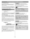
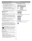
Input gain meter – The input gain meter indicates the average
input signal level of the hardware. The meter is divided into three
color segments:
Amber = Low signal level
Green = Good signal level
Red = High signal level
Signal present indicator – The signal present indicator tells you
if a signal is being received by the hardware:
Inactive = No signal
Green = Good signal
Red = Signal clipping
Opti-source – This is the on/off control for this function. When
on, Opti-source leveling automatically manages the input gain
level so that the full output of the amplifier can be achieved. It
does this by adjusting the input signal level to obtain the desired
amplifier input signal level (+11 dBV). When setting the initial
input gain level, check to make sure that Opti-source is Off. If you
do not see this setting in the control pane, click on More to dis-
play the Opti-source On/Off boxes.
Programmer’s Note: The Opti-source state cannot be
changed when the Opti-voice
®
paging system is on.
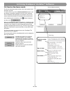
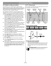
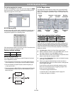
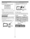
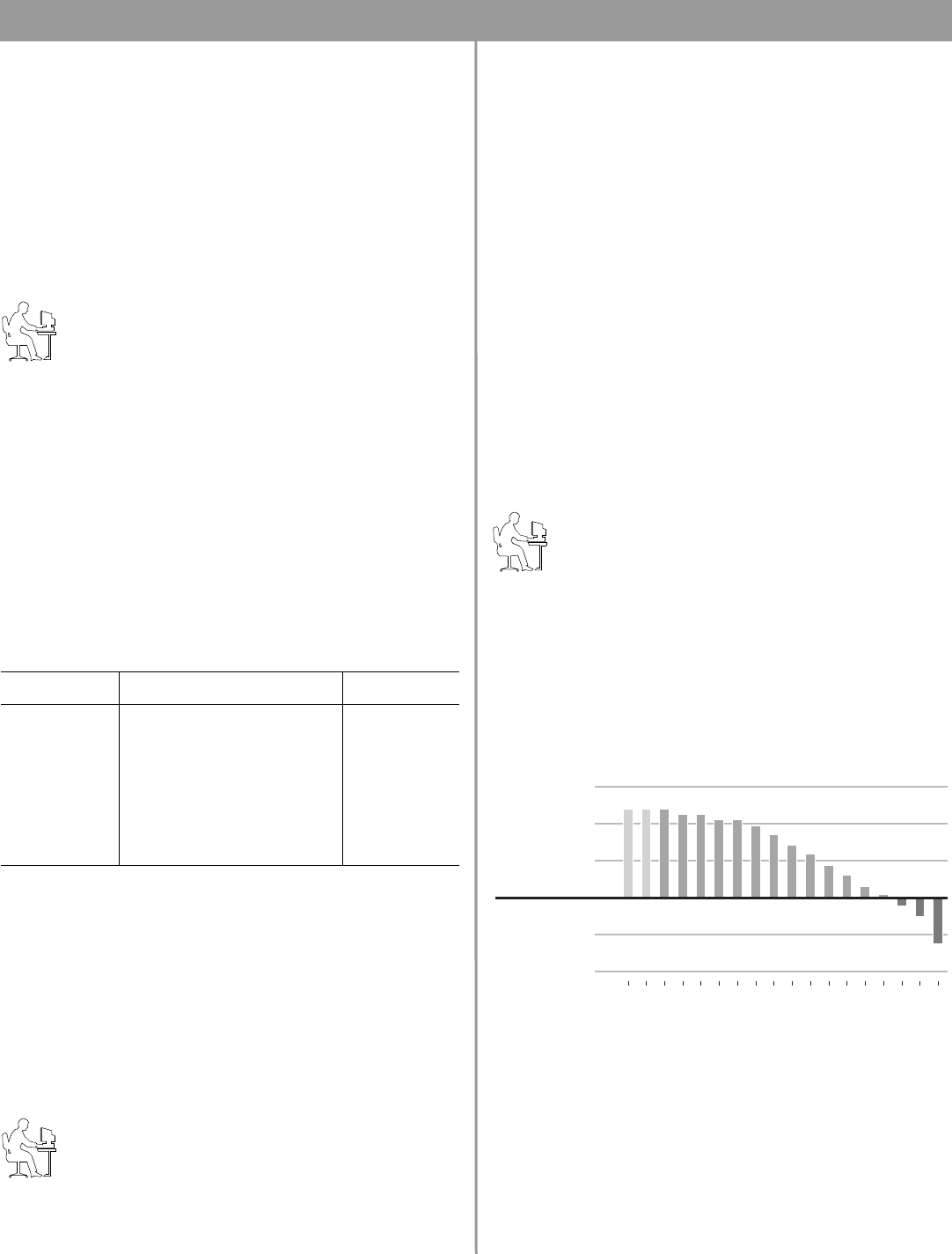
The following chart shows how Opti-source leveling operates.
For sources whose average input signal level is less than –20
dBV, Opti-source leveling will add 20 dB of gain. For sources
whose average signal level is between –20 and 0 dBV, Opti-
source leveling will add the necessary gain so that the average
output of the Opti-source function is +11 dBV. Sources whose
average level is greater than 0 dBV will have gain reduction
applied so that they maintain an average of +11 dBV at the Opti-
source leveling output.
Input signals from –20 to 0 dBV fall within the ideal operating
range for the Opti-source leveling function. This is reflected in the
color scale used for the input gain signal level meter. If your input
signal level is within the green area of –20 to 0 dBV, Opti-source
leveling will effectively manage the input source level.
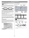
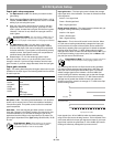
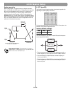
Input Line Input Type(s) Selection Initial Gain
LINE 1 Line 0
LINE 2 Line 0
AUX MIC/
LINE 3
Line (default)
Mic
0
40
PAGE/MIC/
LINE 4
Line
Mic
Line Page
Mic Page (default)
0
40
0
40
-30-25-20-18-15-13-10 -8 -5 -3 0 3 5 8 10 13 15 1
8
-15
-7
-1
9
17
25
Gain (dB)
C
ompression (dB)
Input Signal Level (dBV)