


45 of 80
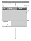
6.0 E4 System Setup
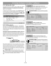
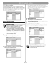
6.3 System setup procedure
The first time you turn on an E4 system it loads its factory
(default) configuration settings. These settings were stored in the
E4 when it was manufactured. Once your PC is fully connected to
the E4 system, you can use the Installer™ software to make
changes to the factory configuration settings.
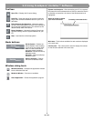
The configuration contains the “start-up” settings for the E4
hardware. Once your work is completed and flashed to the E4
hardware, the new settings become the startup configuration.
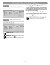
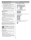
1. Select Output Gain for each zone and mute the output. This
prevents any damage to speakers during this procedure.
This also allows you to work without disturbing any other
people in your work area. See “Output gain” on this page.
2. Set up the ZONE for each output channel. Choose a
Speaker EQ (default is No EQ) for the speakers you are
using. You can use the Subzones table to document your
subzones. See “Zone setup” on page 46.
3. Set up the Input Gain controls for each source. Choose set-
tings for input type, gain, and source leveling. If the input
type is set for microphone use, you can turn phantom power
(+12V) on or off. See “Input gain” on page 47.
4. Set up the Output Gain controls for each zone. Set the min-
imum/maximum gain (volume) limits and the initial gain level.
See “Output gain” on this page.
5. Select Source Assign for each zone and assign sources for
each. See “Source assign” on page 49.
6. Set up the source EQ for MIC/LINE 3 and MIC/PAGE/LINE 4
inputs. See “Source EQ” on page 50.
7. Select Page Set Up. See “Page setup” on page 50.
8. Select EQ for each zone. See “Zone EQ” on page 52.
9. Select the Dynamic EQ state for each zone. See “Dynamic
EQ” on page 53.
10. Set up Auto Volume. See “Auto Volume” on page 53.
11. Create a System Schedule. See the “Set Up Schedule
mode” on page 40.
12. Click the flash configuration button in the upper toolbox. You
will be asked to confirm that you want to save the configura-
tion to the E4 hardware. Once you confirm, the configuration
and scheduling settings are sent to the E4 hardware.
A copy of the Installer™ software design file is also sent to
the hardware.
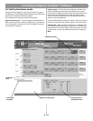
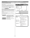
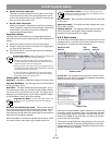
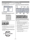
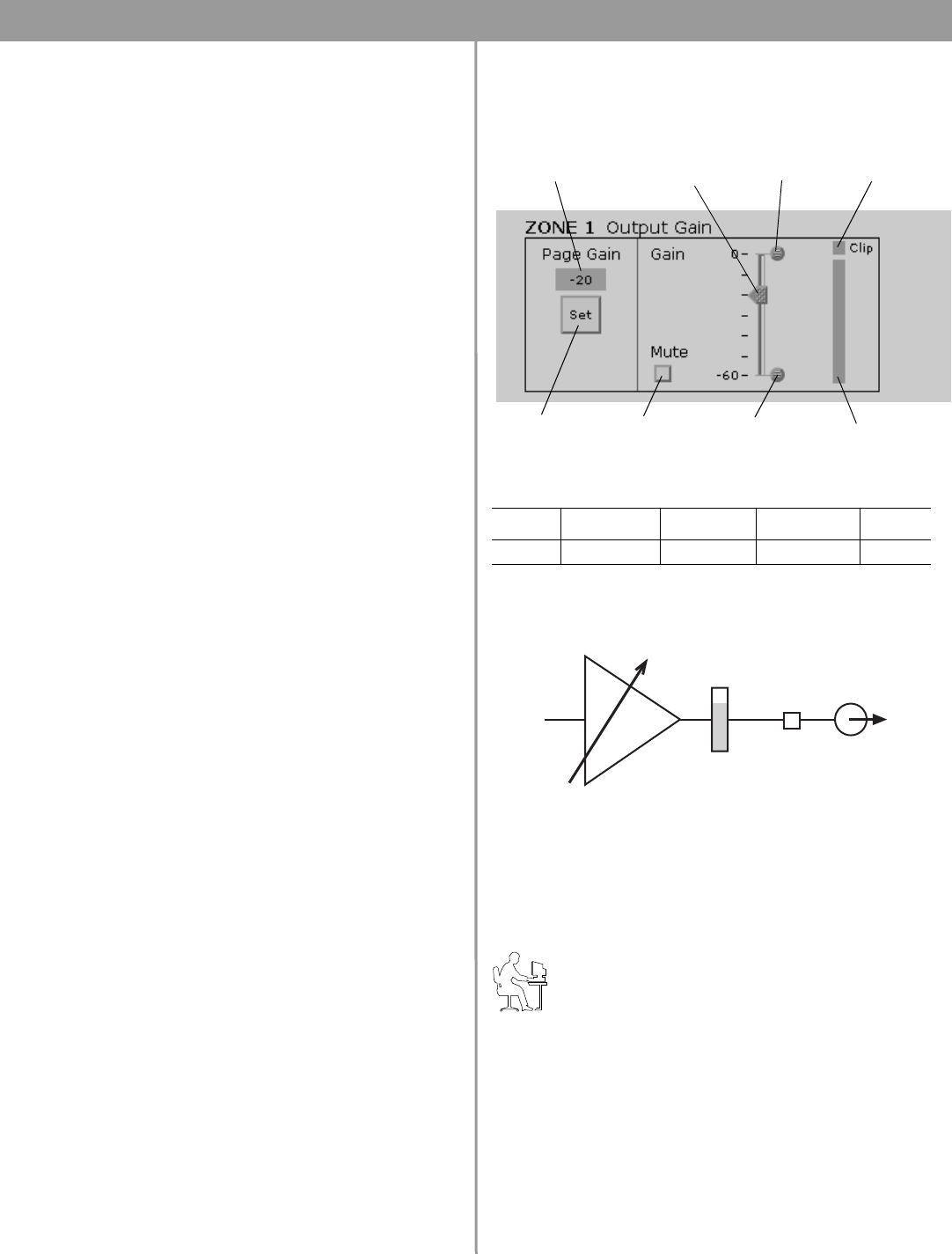
6.3.1 Output gain
The controls in the Output Gain control panel allow you to control
the amplifier output of the E4 system.
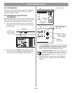
Factory default settings
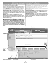
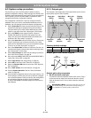
Output gain circuit block diagram
Output gain setup sequence
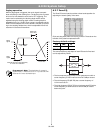
1. Set the maximum output gain.
This sets the maximum allowed volume within a zone. Play a
source that will be used in that zone and raise the volume
slider to the zero level. If it is too loud, lower the maximum
gain stop.
Programmer’s Note: If the source still plays too loud at
the –30 dB setting, you should lower the tap setting on
your speakers for optimal system performance.
Gain Max. Gain Min. Gain Page Gain Mute
–20 dB 0 dB –60 dB –20 dB Off
Max. gain
stop
Clipping
indicator
Gain Slider
(Volume)
Min. gain
stop
Mute
selection
Signal level
meter
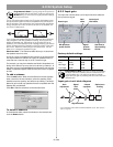
Page gain
setting
Page gain
button
Gain
adjustment
Signal
level
meter
Clipping
detector