


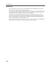
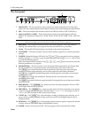
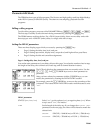
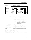
The back panel - 5
D5000
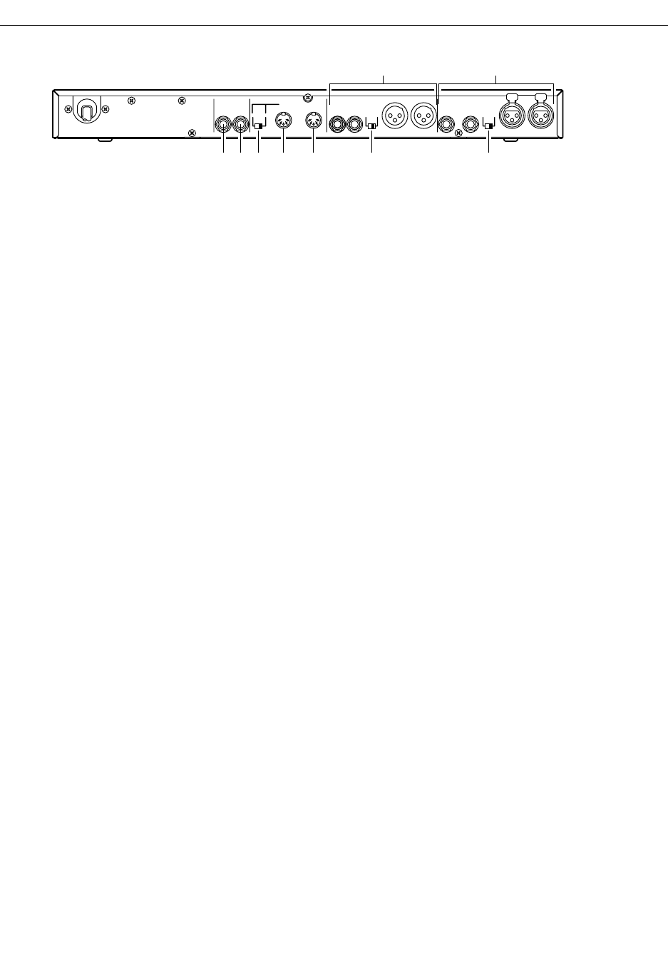
The back panel
1 BYPASS or PROGRAM INC/DEC Footswitch Jack –
The function of this jack is determined by
the FOOT SW FUNCTION parameter of the UTILITY Mode.
If it is set to BYPASS, the footswitch duplicates the function of the [BYPASS] key.
If it is set to PROGRAM, the footswitch allows you to select between a pre-determined range of
program numbers.
2 TRIGGER Footswitch Jack –
A footswitch connected to this jack duplicates the function of the
[TRIGGER] key.
3 MIDI OUT/THRU Switch –
This switch selects either MIDI THRU or MIDI OUT for the MIDI
OUT/THRU connector.
4 MIDI OUT/THRU Connector –
When the MIDI OUT/THRU switch (3 above) is set to OUT,
data originated by the D5000 is transmitted to an external MIDI device.
When the switch is set to THRU, the connector just retransmits data received at the MIDI IN
connector.
5 MIDI IN Connector –
This connector receives data from an external MIDI device.
6 OUTPUT L/R Connectors –
These are the analog stereo outputs from the D5000. Both the XLR-
type connectors and the TRS phone jacks are electrically balanced output connectors.
7 INPUT L/R Connectors –
These are the analog stereo inputs to the D5000. Both the XLR-type
connectors and the TRS phone jacks are electrically balanced input connectors.
Use the "L" (left-channel) connector when you are using a monophonic sound source. Set the
input mode for the source with the INPUT MODE parameter for delay programs (see page 11)
or the TRACK parameter for sampler programs (see page 16 and page 20).
8 Level switches –
Both the input and output connectors may be set to nominal levels of +4 dB or
-20 dB. When connecting the D5000 to other equipment, refer to the specifications of the other
units in order to match the signal levels correctly.
BYPASS
PROGRAM
INC/DEC
TRIGGER
FOOT SW MIDI
THRU OUT
IN
RL
OUTPUT INPUT
RL
20dB +4dB
RL
RL
-20dB +4dB
1
6
2 3 4 5 8 8
7