


4 - The front panel
D5000
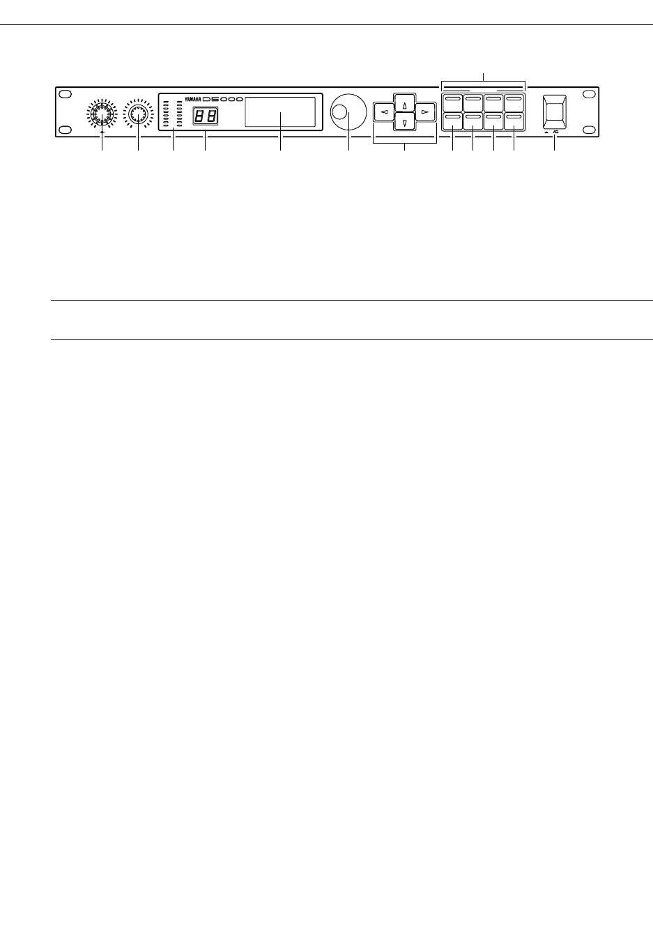
The front panel
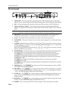
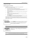
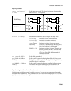
1 INPUT LEVEL –
The two concentric rotary controls are used to adjust the level of the input
signal. The inner control adjusts the left channel and the outer control adjusts the right channel.
2 MIX –
This control adjusts the amount of effect from DRY (no effect) to WET (full effect).
3 Input Level Meters (L and R) –
These stereo meters consist of one eight-segment LED per
channel. The segments correspond to -42 dB, -36 dB, -30 dB, -24 dB, -18 dB, -12 dB, -6 dB, and
CLIP.
4 PROGRAM –
This 2-digit LED indicator shows the current program. When the LEDs are
flashing, this indicates that a new program has been selected but not yet recalled.
5 Screen –
This backlit LCD panel displays the details of the selected parameter.
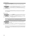
6 DATA ENTRY –
The rotary encoder is used to select another program or to modify parameter
settings.
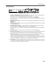
7 CURSOR –
When the Program LED is lit, the [ ^ ] and [ % ] keys are used to select a program
number, the [ < ] ("STORE") key is used to store a program, and the [ > ] ("RECALL") key is used
to recall the selected program.
When the Program LED is turned off, the [ < ] , [ ^ ] , [ > ] , and [ % ] keys are used to select the
different parameters of a program.
8 PARAMETER keys –
These keys allow you to select the different parameters for editing. Each
key has an LED set in it to provide a quick visual indication of the status of the unit.
The [ DELAY ] key controls the delay or freeze parameters. Each key press steps through a
sequence of display pages, allowing you to set the output level and other parameters.
The [ FB ] key controls the feedback parameters. Pressing this key more than once switches
feedback ON or OFF.
The [ MOD ] key controls the modulation. Pressing this key more than once switches
modulation ON or OFF.
The [ DUCK ] key controls the duck or gate threshold. Pressing this key more than once switches
duck ON or OFF.
9 PROGRAM key –
The [ PROGRAM ] key selects one of the 100 stored programs. It has an LED
which lights when the key is pressed.
10 TRIGGER key –
The [ TRIGGER ] key is used to set the tempo for delay parameters or to operate
a freeze or sample and hold program. When the delay DISPLAY UNIT (see page 11) is set to
"TEMPO", the LED will flash in time to the current tempo.
11 UTILITY key –
The [ UTILITY ] key cycles through a number of display pages, allowing you to
set up various system parameters for the unit. It has an LED which lights when the key is
initially pressed.
12 BYPASS key –
The [ BYPASS ] key, when pressed, causes the input signal to bypass the internal
circuitry. It has an LED which lights while BYPASS is active.
13 POWER –
Press to turn the power ON. The last program will be automatically recalled.
NOTE
The meters come after the A-D converters in the signal chain. Therefore, the CLIP LEDs indicate digital
distortion. The input levels should be adjusted so that the CLIP LEDs never light up.
INPUT LEVEL
-00 +10
LR
DRY WET
MIX
LR
CLIP
-6
-12
-18
-24
-30
-36
-42
PROGRAM
PROFESSIONAL DIGITAL DELAY
DATA ENTRY
STORE RECALL
PROGRAM TRIGGER UTILITY BYPASS
DELAY FB MOD DUCK
ON OFF
POWER
CURSOR
PARAMETER
0
1 2 3 4 5 6 9 0 A B C7
8