


Rear Panel 11
CDR1000—Owner’s Manual
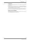
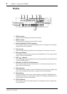
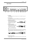
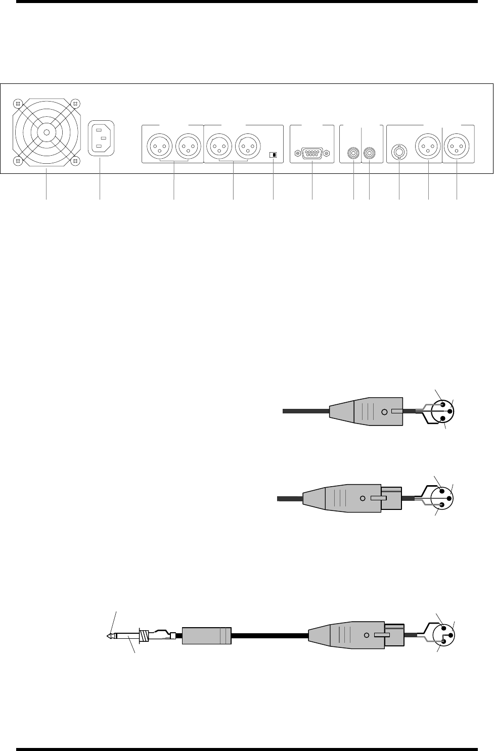
Rear Panel
A Cooling fan
The cooling fan keeps the internal components cool. See “Installation” on page 1 for
more information.
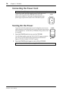
B AC IN connector
This connector is used to connect the CDR1000 to an AC outlet, using the supplied
power cord. See “Connecting the Power Cord” on page 16 for more information.
C ANALOG OUT connectors
These balanced male XLR-3-32 type
connectors output analog playback and
monitor signals. They are wired pin
1–ground, pin 2–hot (+), and pin
3–cold (–).
D ANALOG IN connectors
These balanced female XLR-3-31 type
connectors are used to connect analog
input signals. They are wired pin
1–ground, pin 2–hot (+), and pin
3–cold (–). See “Selecting the Input
Source” on page 25 for more informa-
tion.
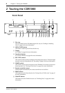
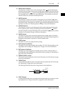
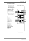
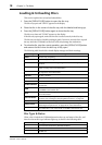
If you need to connect the balanced ANALOG IN or ANALOG OUT to unbalanced
equipment, using phone or phono connectors, link XLR pins 1 and 3, as shown in the
following illustration for an unbalanced phone-plug to female XLR cable.
E ANALOG IN level switch
This switch is used to set the input sensitivity of the ANALOG IN connectors to either
+4 dB or –10 dBV.
ANALOG OUT
AC IN
RL RL
–10dBV +4dB
ANALOG IN PARALLEL
OUT IN
OUT IN
DIGITAL(COAXIAL) DIGITAL(AES/EBU)
WORD
CLOCK
IN
1 3 4 5 6 7 8 9 J K2
Male XLR connector
1 (ground)
3 (cold)
2 (hot)
Female XLR connector
1 (ground)
3 (cold)
2 (hot)
Female XLR plug
1 (ground)
3 (cold)
2 (hot)
1/4" phone plug
Tip (hot)
Sleeve (ground)