


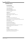
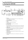
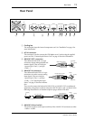
Front Panel
7
CDR1000—Owner’s Manual
J
PREV & NEXT buttons
These buttons are used to select tracks. Pressing the PREV [ ] button during play-
back selects the top of the current track. Pressing it again selects the top of the previous
track. Pressing the NEXT [ ] button during playback selects the top of the next track.
See “Selecting Tracks” on page 23 for more information. These buttons are also used
with the Utility, Erase, and Sync Recording functions.
K
INDEX buttons
These buttons are used to select indexes. Pressing the previous INDEX [ ] button
during playback selects the top of the current index. Pressing it again selects the top of
the previous index. Pressing the next INDEX [ ] button during playback selects the
top of the next index. See “Selecting Indexes” on page 23 for more information.
L
SEARCH buttons
These buttons are used to search backwards and forwards at high speed during play-
back or playback pause. Pressing and holding the backward SEARCH [ ] button
searches backwards. Pressing and holding the forward SEARCH [ ] button searches
forwards. See “Searching” on page 24 for more information.
M
PAUSE button
This button is used to pause and resume playback and recording. When recording is
paused, the CDR1000 waits in Record Standby mode. The PAUSE indicator appears on
the display when playback is paused or in Record Standby mode.
N
STOP button
This button is used to stop playback and recording.
O
PLAY button & indicator
This button is used to start playback and recording. The PLAY indicator lights up dur-
ing playback and recording. See “Playing Discs” on page 21 for more information.
P REC button & indicator
This button is used to engage Record Standby mode. The REC indicator flashes in
Record Standby mode and lights up continuously while recording. See “Recording” on
page 29 for more information.
Q PHONES LEVEL control
This control is used to adjust the volume level of the phones. See “Monitoring” on page
20 for more information.
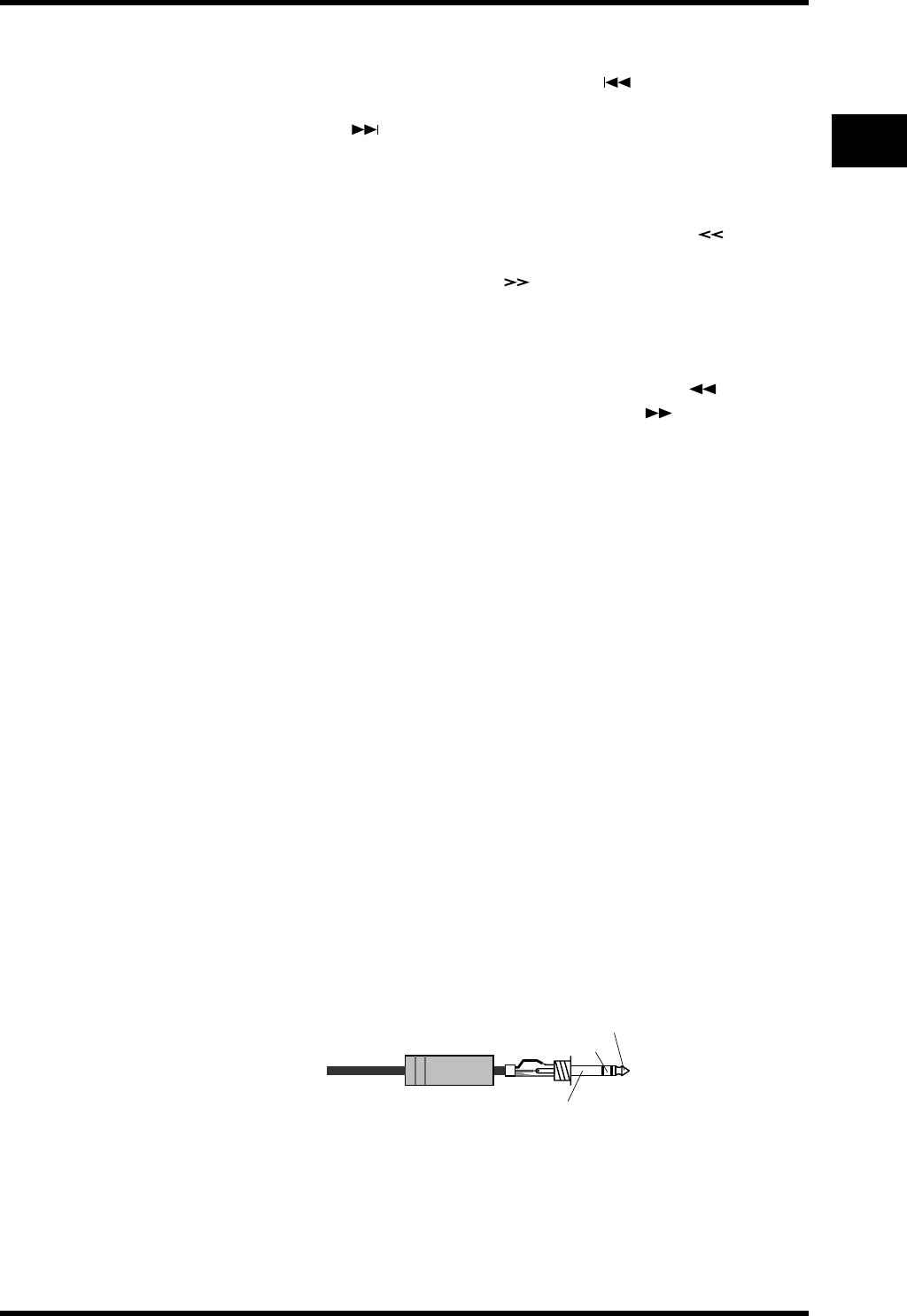
R PHONES jack
A pair of stereo headphones can be connected to this stereo phone jack for monitoring.
See “Monitoring” on page 20 for more information.
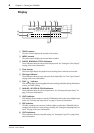
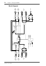
The following illustration shows the wiring scheme for the headphones.
S FOOT SW jack
An optional footswitch can be connected to this jack and used to start and stop record-
ing or playback. See “Using a Footswitch” on page 50 for more information.
1/4" TRS phone plug
Tip (left)
Ring (right)
Sleeve (ground)