


OCTOBER 2006 VXA-320 TAPE DRIVE
13
INSTALLING THE TAPE DRIVE
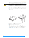
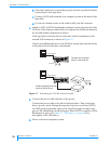
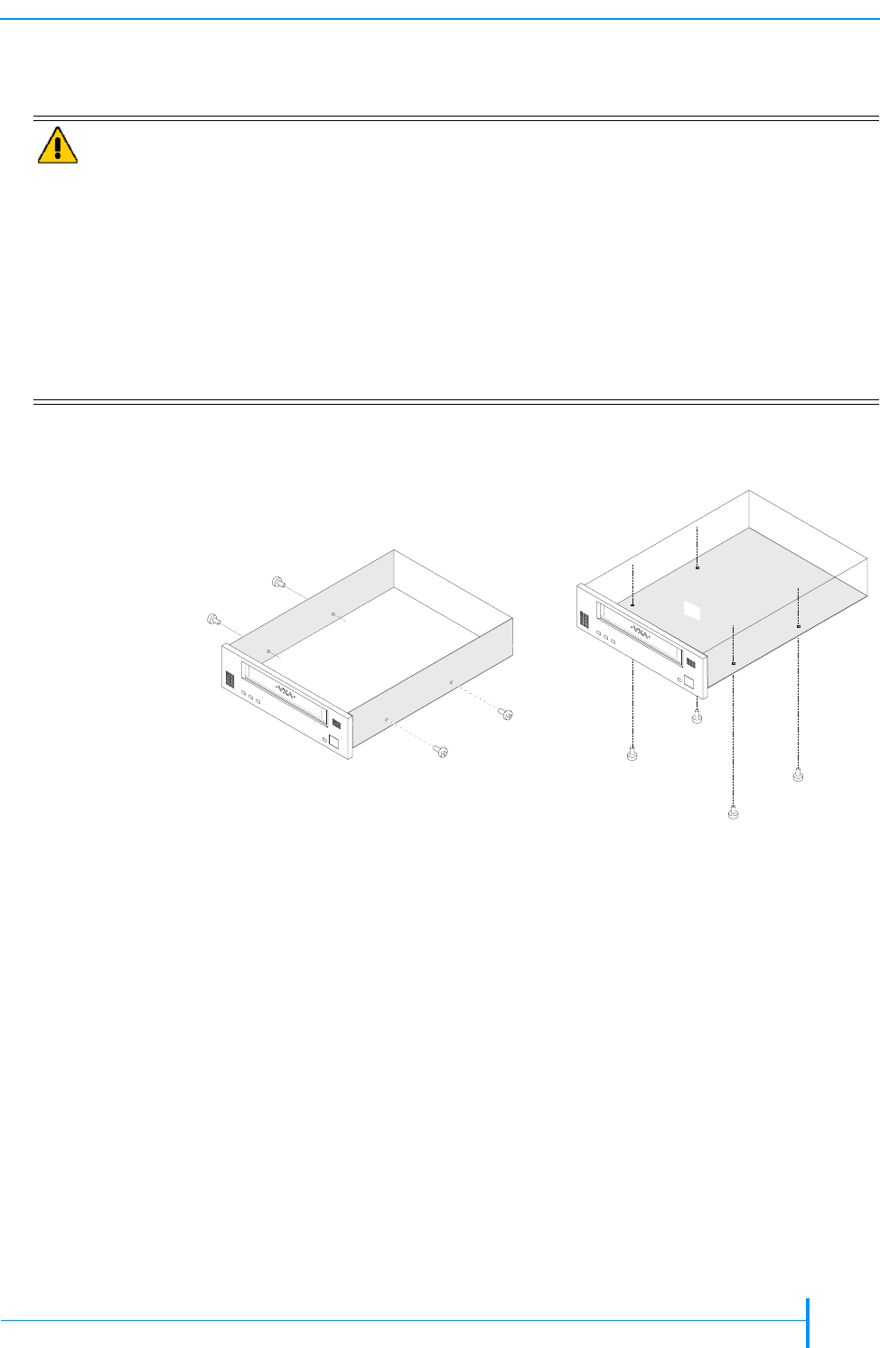
Using the screws provided with the tape drive, secure the tape drive in the
drive bay using one of the screw mounting combinations (see Figure 2-5).
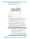
3. Power on the computer system or enclosure.
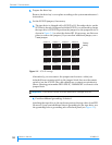
During the tape drive’s power-on self-test, the LEDs scroll sequentially
right to left, then left to right in amber and green. LED 4 illuminates in red
and green. When POST is complete, LED 4 illuminates in green. (See
Table 3-1, “LED states,” on page 20 for a description of the LED states.)
Caution
To avoid damaging the tape drive, follow these precautions:
Use only the M3 × 0.5 × 5 mm Phillips screws. Screw length must not exceed
5mm.
Ensure that the chassis is not distorted. (Alignment to the horizontal or vertical
plane should not exceed ±10°.)
Ensure that no objects (screw heads, cables, or adjacent devices) are pressing
against the frame.
Do not use a combination of the two sets of mounting holes.
Do not obstruct the ventilation fan on the back of the tape drive.
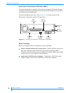
Figure 2-5 Screw mounting configurations (internal model)
3
3
Side mounting
Bottom mount
i
ng