


OCTOBER 2006 VXA-320 TAPE DRIVE
3
COMPONENTS
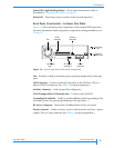
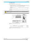
Status LEDs (Light Emitting Diodes) Show status information, which is
described in “Monitoring the LEDs” on page 20.
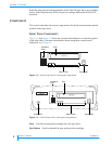
Power LED Shows the power-on status of the external tape drive.
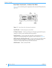
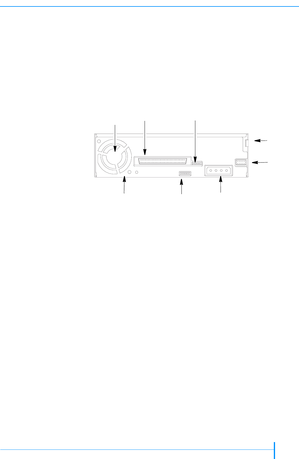
BACK PANEL COMPONENTS – INTERNAL TAPE DRIVE
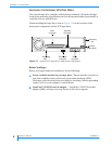
Figure 1-4 shows the back panel components of the internal SCSI tape drive.
For more information about using these components during installation, see
Chapter 2.
Fan Provides cooling to maintain proper operating temperature at the tape
path.
SCSI Connector Used to connect the tape drive to the SCSI bus. This is a
68-pin LVD SCSI connector. (See Tab le 6- 4 for pin assignments.)
Auxiliary Connector Used for tape drive diagnostics.
SCSI ID Jumper Block (SCSI model only) Used to set the SCSI ID.
Grounding Tab and Hole Used to provide additional chassis grounding. (The
mounting screws also provide grounding for the tape drive.)
RF Service Connector Reserved for Tandberg Data Service personnel.
Power Connector Used to connect a power cable from the enclosure’s power
supply. This is a 4-pin connector. (See Tab le 6-4 for pin assignments.)
Figure 1-4 Internal tape drive: back-panel components
SCSI
Grounding
Grounding
RF service
Power
SCSI ID
Auxiliary
connector
connector
tab
hole
connector
connector
jumper block
Fan