OCTOBER 2006 VXA-320 TAPE DRIVE
11
INSTALLING THE TAPE DRIVE
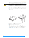
Connect an M3 (0.25 in.) female spade connector from the host to the
tape drive’s grounding tab.
or
Use an M3
× 0.5 mm × 5 mm machine screw to connect a grounding wire
to the grounding hole.
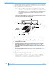
4. Connect the SCSI cable.
a. Check the connector to ensure that no pins are bent or pushed in before
connecting it to the tape drive.
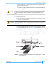
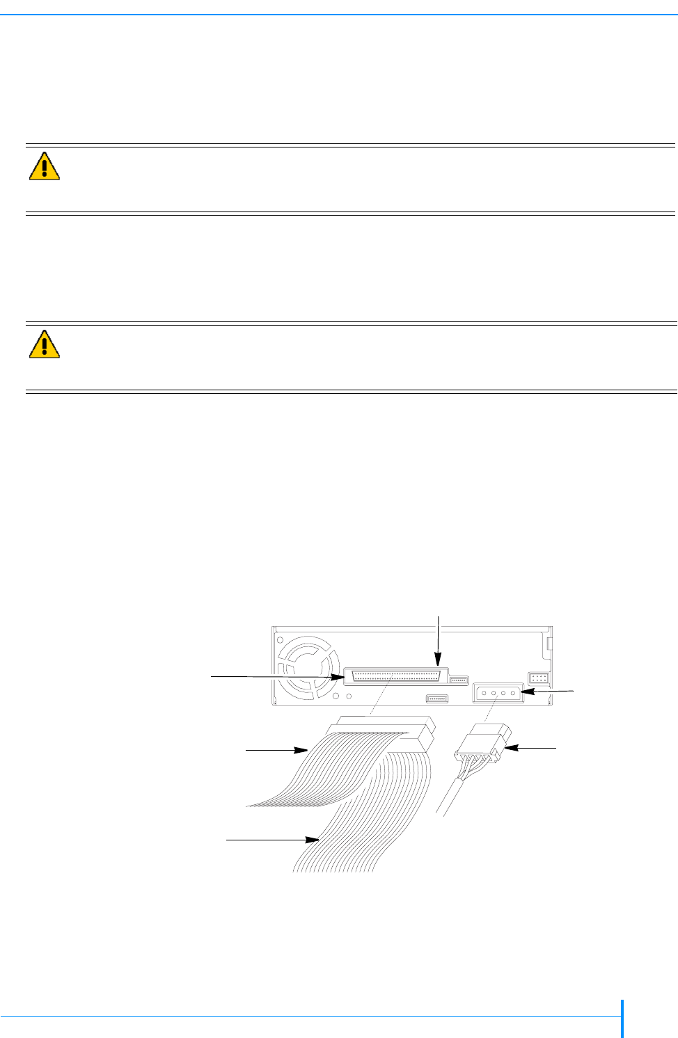
b. Connect one of the enclosure’s internal SCSI cables to the SCSI connector
on the back of the tape drive (see Figure 2-3). This cable must meet the
guidelines in “SCSI Cable Requirements,” beginning on page 41.
Note: If desired, you can mount the tape drive (see page 12) before you
connect the SCSI cable, the terminator (if required), and the power
cable to the back. However, if the cables are difficult to access in the
enclosure, you should extend the cables out through the drive bay
and connect them before mounting the tape drive.
Caution
Do not use a screw other than the type specified for attaching the grounding wire,
or you may damage the internal components. Screw length must not exceed
5mm.
Caution
To avoid damaging the tape drive, make certain you connect pin 1 on the cable to
pin 1 on the tape drive. Pin 1 is on the right, top row of the connector pins (see
Figure 2-3).
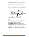
Figure 2-3 Connecting the SCSI cable and power cable (another device is the last
device on the bus)
to SCSI
adapter card
to additional
SCSI device
SCSI
connector
Power
connector
from host computer
power supply
Pin 1


