


4. ELECTRICAL CONNECTIONS
4.1 MST2100: NEMA 1 En clo sure
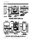
A. Re view the MST2100 and MST2400 di men sional
draw ings.
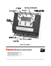
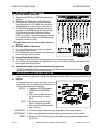
B. Re fer to the MST2000 Ter mi nal Block Draw ing.
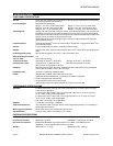
C. MST2000 In stru ment Elec tri cal Con nec tions are
cage clamp style for 12-24 AWG. Wire should be
stripped back a min i mum of 3/16" inches (5mm).
D. The MST2000 Multivariable dif fer en tial pres sure
trans mit ter is a HART® com pat i ble loop-powered
4-20 milliamp trans mit ter. Power con nec tion is
made at the two left ter mi nal po si tions marked
LOOP+ and LOOP-. Nom i nal power sup ply volt age
is 24 volts DC which al lows up to 600 ohms se ries
re sis tance in the loop cir cuit.
þFor HART® ap pli ca tions, min i mum loop re sis tance is
250 ohms.
4.2 MST2400: NEMA 4X En clo sure
A. A ½" Liq uid Tite con duit con nec tion is lo cated on
the bot tom of the En clo sure.
B. Con duit should be in stalled to pre vent con den sa tion
from col lect ing in the in stru ment.
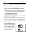
4.3 In te gral Power Sup ply Op tion.
A. The In te gral Power Sup ply Op tion re quires an ex ter nal 120 Volt Power Sup ply.
B. A six (6) po si tion screw type ter mi nal block and ½" Liq uid Tite Con duit con nec tion are sup plied with
the In te gral Power Sup ply Op tion.
4.4 Ca na dian Stan dards As so ci a tion Hazardous Area Ap provals
The MST2100 and MST2400 have been ap proved by CSA for haz ard ous area in stal la tions.
See Sec tion 15 for de tails or con tact the fac tory.
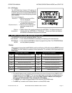
5. LCD DISPLAY and INTEGRAL KEY PAD
All con trols and in di ca tors are Lo cated on the front panel of the MST2000. Re fer to the LCD & Key Pad
Draw ing.
5.1 Key Pad
All pro gram ming and con trol op er a tions are per -
formed us ing four (4) pushbuttons on the key pad.
Fol low ing are sum ma ries of each key.
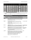
MODE: ! Tog gles the MST2000 be tween
RUN Mode and PROGRAM
Mode.
! Also used to change the edit cur -
sor when en ter ing a numeric
value.
EDIT: ! Se lects the pa ram e ter to edit
when in Pro gramming Mode.
! Also saves the ed ited pa ram e ter
data to memory.
INCREMENT: ! In cre ments (steps for ward) through pa ram e ters and/or nu meric val ues.
DECREMENT: ! Dec re ments (steps back wards) through pa ram e ters and/or nu meric val ues.
RESET: ! Re sets the CPU. Re starts pro gram and loads in pro grammed vari ables stored in
the E-Prom
ELECTRICAL CONNECTIONS OPERATION MANUAL
Page 10 MST2000 Multivariable SMARTFLOW
®
Transmitter Brandt Instruments, Inc.