


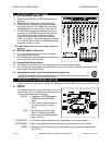

1. MOUNTING AND PROCESS CONNECTIONS
The MST2000 can be mounted in any di rec tion. There may be a mi nor ef fect on Zero
that can be cor rected by the setup pa ram e ters.
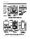
1.1 MST2100: NEMA 1 En clo sure
A. Re view the di men sional draw ing on page 5.
B. Pro cess con nec tions are via 1/8" NPT fe male ports lo cated on the bot tom of the hous ing. The high
pres sure port is la beled “HIGH”, the Low pres sure port is la beled “LOW” on the mount ing plate.
1.2 MST2400: NEMA 4X En clo sure
A. Re view the di men sional draw ing on page 5.
B. With out a con tin u ous purge op tion, pro cess air should be non-corrosive and dry. If a con tin u ous
purge op tion is in stalled please re view sec tion 2 on the con tin u ous purge. The con tin u ous purge
must be bal anced.
C. Pro cess con nec tions are via 1/4" NPT fe male ports lo cated on the bot tom of the en clo sure. The high
pres sure port is la beled “HIGH”, the Low pres sure port is la beled “LOW”.
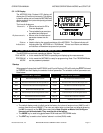
1.3 Three Valve Man i fold
A. It is rec om mended that a three valve man i fold be in stalled in the pro cess, un less a con tin u ous
purge is in stalled . A three valve man i fold is avail able from the fac tory. It is in stalled in the pro cess
lines to iso late the pro cess sig nal dur ing in stal la tion and/or re moval of the MST2000 thus pre vent ing
pos si ble trans ducer over-pressurization and to zero trans mit ter.
þNotes:
& Be fore con nec tions are made blow out pro cess lines throughly.
& It is rec om mended that pipe thread tapes not be used on pneu matic pip ing.
& Soap test all joints and fit tings for leaks.
& Pro cess lines should be the same di am e ter and ap prox i mately the same length.
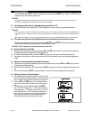
2. CONTINUOUS PURGE OPTION
The MST2400 can be or dered with a Con tin u ous
Purge Op tion. This op tion sup plies a con tin u ous
pneu matic purge to a Thermo Brandt pitot flow
sen sor to keep the sens ing ports free from plug -
ging dur ing op er a tion. There are Purge Bal ance
ad just ments lo cated on the front panel which
pro vide for the ze ro ing of pro cess air re sis tance.
If the Con tin u ous Purge Op tion has been or -
dered, please read the fol low ing setup in struc -
tions. The Con tin u ous Purge Op tion must be
bal anced once the pro cess is con nected to
the MST2400.
A 1/4" NPT fe male air sup ply port is pro vided on
the bot tom of the en clo sure for the Purge.
An in ter nal fil ter is sup plied with the unit, but air
sup ply should also be fil tered and reg u lated.
þPROCESS LINE LENGTH & SIZE
& When a con tin u ous purge op tion is used, the pro cess
lines (Hi and Low lines) must be the same di am e ter
(pref er a bly 3/8" or larger) and the length of each line
should be the same within +/- 5%.
þIMPORTANT:
& The Con tin u ous purge op tion air sup ply should be only clean, in stru ment qual ity air and should be greater than 20
psi (1.4 bar) and not ex ceed 100 psi (6.9 bar). A pre-filter should be in stalled in the sup ply line if the air qual ity is
sus pect. A 5 mi cron fil ter and a 0.3 mi cron co ales cent fil ter are rec om mended. Fail ure to pro vide clean, in stru ment
qual ity air through the Con tin u ous Purge can cause the MST2000 to give er ratic read ings. Fail ures at trib uted to a
con tam i nated air sup ply are not cov ered un der the war ranty.
MOUNTING AND PROCESS CONNECTIONS OPERATION MANUAL
Page 8 MST2000 Multivariable SMARTFLOW
®
Transmitter Brandt Instruments, Inc.
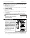
þNote: MST2000 DP sen -
sor max i mum op er at ing
static pres sure is 25
PSID.