


E. Latched Output: Enabling the Latched Output bit will cause any active alarm to become latched
and held active even if the alarm condition clears. Any ‘latched’ alarms can be cleared during RUN
mode by pressing the EDIT key (if the active alarm(s) are no longer active). After pressing the EDIT
key, any latched alarms that are no longer active will be cleared and any alarms that are still active
will remain latched.
F. Digital Out1: Enabling the Digital Out1 bit will cause the digital output channel (OUT1) to change to
the LOW state if any alarm is active.
þNote: The OUT1 (and OUT2) channels are ‘open collector’ style outputs. The user must externally
connect an active pull-up voltage to the output pins for proper operation. The maximum external pull-up
voltage that can be applied to the output pins is 24 volts DC.
G. Ex ter nal Con stants: En abling the Ex ter nal Con stants bit will cause the pro grammed con stants for
tem per a ture or pres sure to be used in the mass flow cal cu la tions if ei ther the ex ter nal tem per a ture
or pres sure in puts are se lected and in fault con di tions.
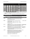
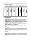
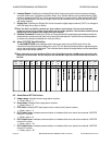
9.4 Alarm ‘STATUS’ Word Def i ni tion
The ALARM STATUS word indicates which alarms are active during RUN mode. Since the
individual binary bits cannot be displayed on the LCD, the decimal word equivalent representing the
active alarm status bits is displayed. The individual alarm status bit assignments and the associated
binary values are shown below.
þNote: If alarms are ac tive, the alarm ICON on the LCD will be lit and the ALARM sta tus value will be dis -
played ev ery 10 sec onds. The user may also use the INC/DEC keys to ac cess the alarm sta tus value on
the LCD.
BIT
16
BIT
15
BIT
14
BIT
13
BIT
12
BIT
11
BIT
10
BIT
9
BIT
8
BIT
7
BIT
6
BIT
5
BIT
4
BIT
3
BIT
2
BIT
1
32768 16384 8192 4096 2048 1024 512 256 128 64 32 16 8 4 2 1
9.5 Alarm Sta tus ‘BIT’ Def i ni tions
A. Under-range: Indicates Under-range alarm is active.
• Bi nary value = 1.
B. Over-range: Indicates Over-range alarm is active.
• Bi nary value = 2.
C. RTD Fault: Indicates RTD fault (open circuit or short circuit) alarm is active.
• Bi nary value = 4.
D. ISO Comm1 error: Indicates communication or hardware fault error alarm from external 4-20 PCB
channel 1 is active.
• Bi nary value = 8.
E. ISO Comm2 error: Indicates communication or hardware fault error alarm from external 4-20 PCB
channel 2 is active.
• Bi nary value = 16.
F. ISO Comm3 error: Indicates communication or hardware fault error alarm from external 4-20 PCB
channel 3 is active.
• Bi nary value = 32.
ALARM PROGRAMMING INFORMATION OPERATION MANUAL
Page 20 MST2000 Multivariable SMARTFLOW
®
Transmitter Thermo Brandt In stru ments