


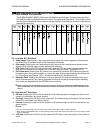
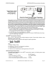
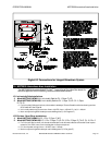
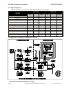

15.5 Notes for MST2000 I.S. In stal la tion Draw ing SC37-4000-00
1.
For I.S. In stal la tions, field wir ing shall be in stalled in ac cor dance with Ca na dian Elec t ri cal Code and/or Na tional
Elec tri cal code ANSI/NFPA 70, Ar ti cle 504-30
2.
Wiring ca ble shall be 24 AWG or heavier, sep a rate shielded pairs.
3.
The ground ing con nec tion be tween the safety bar rier and earth ground must be less than 1 ohm.
4.
Con trol room equip ment must not gen er ate more than 250 Volts rms.
5.
Safety Bar riers must be of ap proved types and used in an ap proved con fig u ra tion where the trans mit ter Vmax
value is greater than the bar rier Voc rat ing and the trans mit ter Imax value is greater than the Bar rier Isc rat ing.
6.
The trans mit ter in put ca pac i tance (Ci) plus the to tal ca ble ca pac i tance for each loop must not ex ceed the bar rier
Ca rat ing.
7.
The trans mit ter in put in duc tance (Li) plus the to tal ca ble in duc tance for each loop must not ex ceed the bar rier La rat ing.
8.
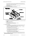
Trans mit ter en clo sure must be grounded to earth ground us ing the pro vided ground lug on the en clo sure.
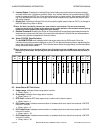
9.
The MST2000 Trans mit ter is In trin sically Safe for:
! Class I, Di vi sion 1, Groups C and D
! Class II, Di vi sion 1 Groups E, F and G.
10.
Loop en tity pa ram e ters per cir cuit are:
! Vmax = 40 VDC
! Imax = 165mA
! Ci = 0uF
! Li = 240uH
11.
Use only CSA ap proved I.S. Pres sure trans mit ters where the Vmax and Imax of the trans mit ter is greater than the Voc and Isc of the bar rier.
The Ci and Li of the trans mit ter must be in cluded in sys tem to tal ca pac i tance and in duc tance cal cu la tion and must be less than bar rier Ca
and La Rat ings.
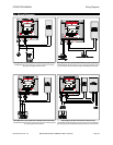
12.
Ap proved meth ods for sep a ra tion of each loop are:
! Run ning Loops in sep a rate ca bles
! Run ning Loops in sep a rate shields
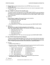
13.
When con nect ing HART com mu ni ca tor the Vmax and Imax of the com mu ni ca tor must be greater than the Voc and Isc of the bar rier. Voc of
com mu ni ca tor plus Voc of bar rier must be less than Vmax of trans mit ter, ISC of Com mu ni ca tor plus Isc of Bar rier must be less than Imax of
Trans mit ter. Li of Trans mit ter plus Li of Com mu ni ca tor must be less than La of Bar rier, Ci of trans mit ter plus Ci of Com mu ni ca tor must be
less than Ca of Bar rier.
14.
Use only listed and ap proved dust tight seal for Class II and Class III Haz ard ous Lo ca tions.
15.
Other wire ter mi nals not avail able for use on In trin sically Safe ver sion
16.
No re vi sions shall be made with out no ti fi ca tion of Ap proval Agency(s).
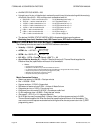
16. Cal i bra tion of the MST2000
Ba sic cal i bra tion of the MST2000 Se ries trans mit ters is done in two parts: 1) set ting the 4-20 mA out put
from the dig i tal to an a log con verter and 2) set ting the 0 & 100% val ues of the dis played DP. Both parts
are done by the set ting of pa ram e ters, en tered via the in te gral key pad.
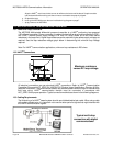
16.1 OUTPUT mA CALIBRATION
A. ZERO and SPAN of the mA out put are set by the OUTPTO and OUTPTG pa ram e ters, re spec tively.
You do not need to ap ply any DP sig nal for the mA cal i bra tion, only an ac cu rate mA test me t er is re -
quired.
B. Fol low ing the pro ce dures of Sec tion 7, en ter the PROGRAMMING Mode and se lect the OUTPTO
pa ram e ter. The ex ist ing value of OUTPUT OFFSET will be dis played.
C. Press the EDIT/SAVE key once to force the dig i tal to an a log con verter to its 0% out put value and to
al low you to ad just the out put to ex actly 4.00mA as read on a mA test me ter. Use the INCREMENT
& DECREMENT keys as needed.
D. Press the EDIT/SAVE key to exit the edit mode and save the OUTPUT OFFSET value (even if there
was no ad just ment made). Now step to the OUTPTG pa ram e ter to dis play the ex ist ing value of
OUTPUT GAIN.
E. Press the EDIT/SAVE key once to force the dig i tal to an a log con verter out put to its 100% value and
to al low you to ad just the out put to ex actly 20.00mA as read on a mA test me ter. Use the
INCREMENT & DECREMENT keys as needed.
F. Press the EDIT/SAVE key to exit the edit mode and save the OUTPUT GAIN value. This com pletes
the out put mA cal i bra tion.
G. Exit the PROGRAMMING Mode, by press ing the MODE key, or con tinue with the DP cal i bra tion.
OPERATION MANUAL Cal i bra tion of the MST2000
Brandt Instruments, Inc. MST2000 Multivariable SMARTFLOW
®
Transmitter Page 33