


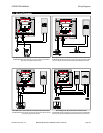
b. Ex ter nal Tem per a ture Trans mit ter ISO Mod ule . Re view the Pro gram Pa ram e ters in sec tion 8.
i. Con nect a 4-20 mA source to the Ex ter nal Tem per a ture Trans mit ter ISO Mod ule in put ter mi nals
(marked EXTIN 2). See ter mi nal block draw ing on page 7.
ii.
Make sure pa ram e ter TMPSRC (Tem per a ture Source) is set to 1 (1 = EX Ter nal).
iii.
Set the EX_TPZ (Tem per a ture Zero) pa ram e ter.
iv.
Set the TPZCAL (Tem per a ture Zero Cal i bra tion) pa ram e ter.
.
! Press the Edit key. Dis play will change to read IN4mA.
. ! Ap ply 4.0 milliamps. Press the Edit Key to read and store the 4 milliamp cal i bra tion value.
v.
Set the EX_TPS (Tem per a ture Span) pa ram e ter.
vi.
Set the TPSCAL (Tem per a ture Span Cal i bra tion) pa ram e ter.
.
! Press the Edit key. Dis play will change to read IN20mA.
. ! Ap ply 20.0 milliamps. Press the Edit Key to read and store the 20 milliamp cal i bra tion value.
12.2 Dig i tal In put / Out put Mod ule In stal la tion
A. Thermo Brandt Part Number FP37-OPTN-DIO
a. The Dig i tal I/O mod ule al lows the MST2000 to ac cept one (1) dig i tal in put and out put (1) dig i tal out -
puts.
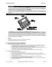
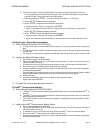
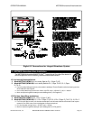
b. The Dig i tal I/O mod ule must be in stalled on the right most con nec tor. See pho to graph and draw ings
in this sec tion.
c. The Dig i tal I/O module will be shipped in a sealed bag along with stand offs (2) and in struc tion sheet.
B. Installing the Digital I/O Module Option.
a. Dis con nect all power from the MST2000.
b. Take off the MST2000 Cover by re mov ing the 4 flat head screws. It is not nec es sary to re move the
Main Board from the hous ing.
c. Lo cate the slot, con nec tor and two mount ing holes for the Dig i tal I/O module on the Main Board.
d. Re move the Dig i tal I/O module and two (2) stand offs from the bag.
e. Snap the standoffs into the two holes lo cated on the Main Board as shown in the draw ing. Note the
ori en ta tion of the stand offs.
f. Align the Dig i tal I/O mod ule such that con nec tor will be on the bot tom of the board. Snap the module
into the stand offs while mak ing sure the con nec tor and header are prop erly aligned.
g. Re place the cover.
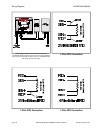
h. Hook up the MST2000 as per the ter mi nal block wir ing di a gram on page 7.
i. Ap ply Power to the MST2000.
C. For Dig i tal I/O wiring con fig u ra tions see sec tion 14.
12.3 HART
®
Com mu ni ca tions Mod ule
A. Thermo Brandt Part Number FP37-OPTN-HART
a. The HART
®
Com mu ni ca tion mod ule al lows the MST2000 to com mu ni cate with stan dard HART
®
In -
ter faces.
b. The HART
®
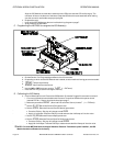
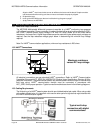
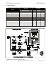
Com mu ni ca tion mod ule must be in stalled on the up per left most con nec tor. See pho to -
graph and draw ings in this sec tion.
c. The HART
®
Com mu ni ca tion mod ule will be shipped in a sealed bag along with stand offs (2) and in -
struc tion sheet.
B. In stalling the HART
®
Com mu ni ca tion Mod ule Op tion.
a. Dis con nect all power from the MST2000.
b. Take off the MST2000 Cover by re mov ing the 4 flat head screws. It is not nec es sary to re move the
Main Board from the hous ing.
c. Lo cate the slot, con nec tor and two mount ing holes for the HART
®
mod ule on the Main Board.
d. Re move the HART
®
mod ule and two (2) stand offs from the bag.
e. Snap the Stand offs into the two holes lo cated on the Main Board as shown in the draw ing. Note the
ori en ta tion of the stand off.
f.
OPERATION MANUAL OPTIONAL MODULE INSTALLATION
Brandt Instruments, Inc. MST2000 Multivariable SMARTFLOW
®
Transmitter Page 25