


MODEL NUMBER
OPERATION MANUAL
Brandt Instruments, Inc. MST2000 Multivariable SMARTFLOW
®
Transmitter Page 5
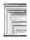
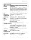
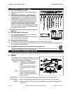
MST24 1 1 1 H D 2S 1 0 P
ISOLATED INPUT MODULE: Ab so lute Pres sure Trans mit ter
0 = None
1 = Iso lated In put Mod ule: Ac cepts 4-20mA in put sig nal from an Ex ter nal Ab so lute Pres sure Trans mit ter. u
2 = Isolated Input Module with Integral Absolute Pressure Transmitter, 0-25 PSI (0-1.7 bar) range standard. Consult factory for
other ranges. MST2400 only. Requires Integral 24V Power Supply. See Output option 2 below.
ISOLATE
D INPUT
MODULE: Tem per a ture Trans mit ter
0 = None
CERTIFICATION
0 = None
1 = CSA Ap proved In trin sically Safe
2 = CSA Ap proved Di vi sion 2.
Review Sec tion 15 of this man ual for ap proval in for ma tion.
COMMUNICATIONS
MODULE
0 = None
H = HART
®
Com mu ni ca tions Mod ule. u
DIGITAL I/O
MODULE
0 = None
D = Dig i tal I/O Mod ule with 1 In put, 1 Out puts. v
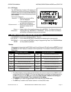
PRESSURE RANGES
1S = Stan dard Range 1 Max. Span: 0-0.10” ( 0 to 2.54mm) W.C. Turn down to 0.010” (0.254mm)W.C. (10:1).
2S = Stan dard Range 2 Max. Span: 0-0.25” ( 0-6.35mm) W.C. Turn down to 0.025“ (0.635mm) W.C. (10:1).
3S = Stan dard Range 3 Max. Span: 0-1.00“ (0-25.4mm) W.C. Turn down to 0.10“ (2.54mm) W.C. (10:1).
4S = Stan dard Range 4 Max. Span: 0-4.00” (0-101.6mm) W.C. Turn down to 0.40” (10.16mm) W.C. (10:1).
5S = Stan dard Range 5 Max. Span: 0-16.0” (0-406.4mm) W.C. Turn down to 1.60” (40.64mm) W.C. (10:1).
6S = Stan dard Range 6 Max. Span: 0-50.0” (0-1270.0mm) W.C. Turn down to 5.00” 127.0mm) W.C. (10:1).
CR = Com pound RangeCon sult fac tory. Sup ply de sired Com pound Range.
All max i mum pres sure ranges have a turn down of 10:1.
Spec ify Pres sure Range # in model num ber (ex am ple 1S or CR).
Stan dard Ranges: MST2000 will be cal i brated at Max i mum Span. If an Ini tial Range Set ting is de sired, sup ply with
or der and unit will be shipped with this Ini tial Range pre set. (Ex am ple: 3S set to 0 to 0.5” W.C.).
Com pound Ranges: MST2000 will be cal i brated at de sired Com pound Range. Sup ply com pound range with or der
(ex am ple: -0.25 to +0.25” W.C.).
All spans will be cal i brated in Inches of W.C. Other Units of mea sure will be con verted to Inches of W. C.
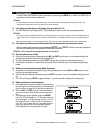
OUTPUT & VERSION. See Note Be low.
1 = 4-20mA Out put. Eng lish Units Ver sion. u
2 = 4-20mA Out put with In te gral 120VAC to 24VDC Power Sup ply. 120VAC
Source Re quired. MST2400 only. Eng lish Units Ver sion.
3 = 4-20mA Out put. Met ric Units Ver sion. u
4 = 4-20mA out put with In te gral 120VAC to 24VDC Power Sup ply. 120VAC Source
Re quired. MST2400 only. Met ric Units Ver sion.
OPTIONS
0 = None
B = In te gral High Pres sure Blowdown Sys tem. MST2400 Only. Re quires
Dig i tal I/O Mod ule. 120VAC source re quired. Reg u lated air sup plied to
100 PSIG. En clo sure size will change. Con sult Fac tory for spec i fi ca tions
and avail abil ity.
P = Con tin u ous Purge to Flowmeter. MST2400 Only. Spans of 0.25” W.C.
(6.35mmWC) or greater. A fil tered air sup ply source of 20 to 100 PSI
(1.4 to 6.9 bar) is re quired. u
ACCESSORIES
0 = None
P = Pipe Mount. MST2400 Only.
MST2000’s with Eng lish or Met ric Unit Ver sions are avail able but must be se lected at time of or der and con fig ured at
the fac tory. IT IS NOT A FIELD SELECTABLE OPTION.
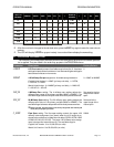
SERIES: LOOP POWERED MULTIVARIABLE SMARTFLOW
TM
TRANSMITTER
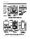
MST21 = MST2100, NEMA 1 Panel Mount En clo sure, Dif fer en tial Pres sure Con fig u ra tion & Non-isolated 4 Wire RTD In put Stan dard. u
MST24 = MST2400, NEMA 4X, Fi ber glass En clo sure, Dif fer en tial Pres sure Con fig u ra tion & Non-isolated 4 Wire RTD In put Stan dard. u
u De notes op tions & fea tures avail able with CSA In trin sically Safe
and Di vi sion 2 haz ard ous area ap prov als.
v De notes op tions & fea tures avail able with CSA Di vi sion 2 Ap -
provals Only.
Re view Sec tion 15, for CSA ap proval in for ma tion.